Rocky The Robot
Intro
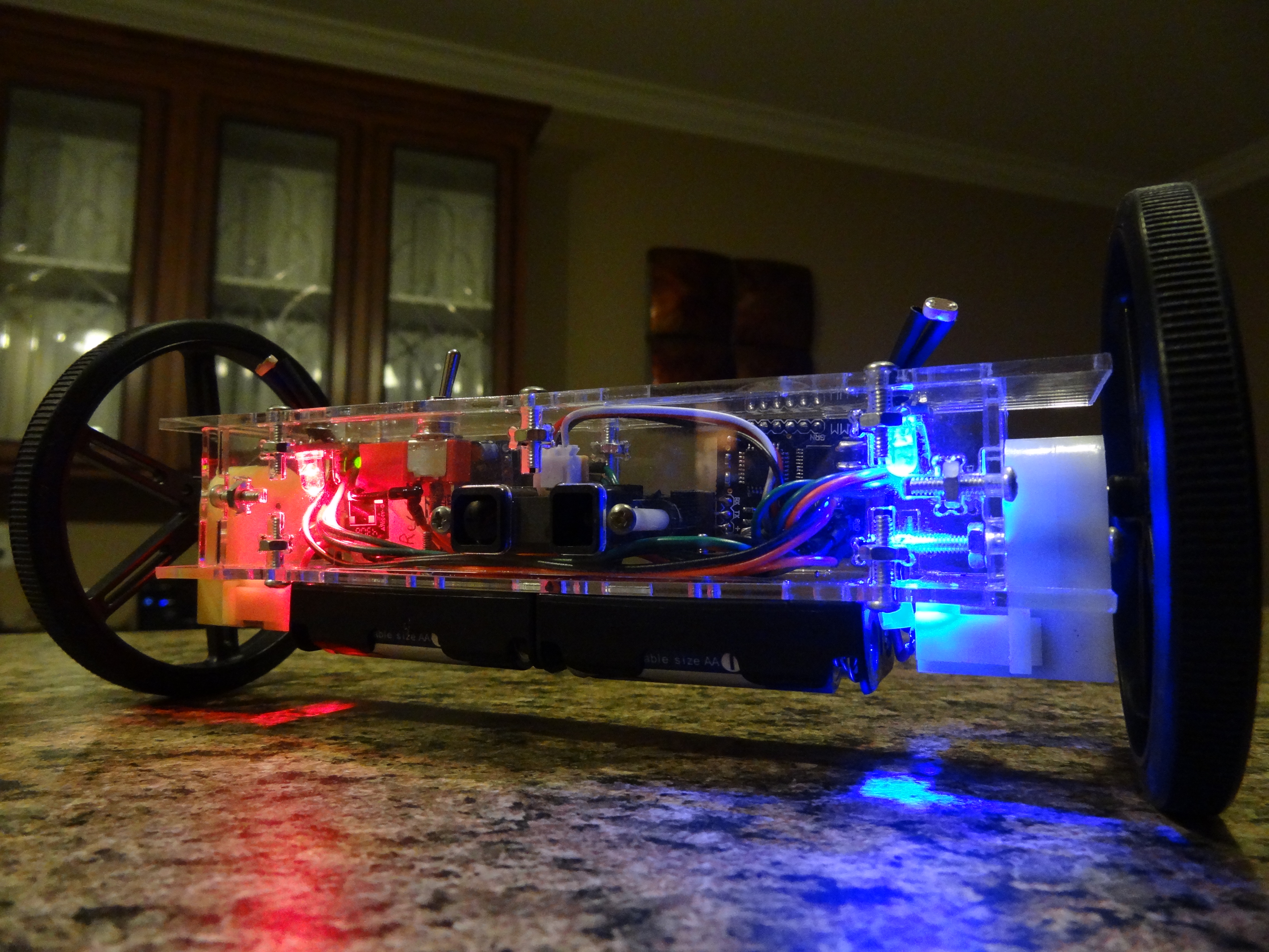
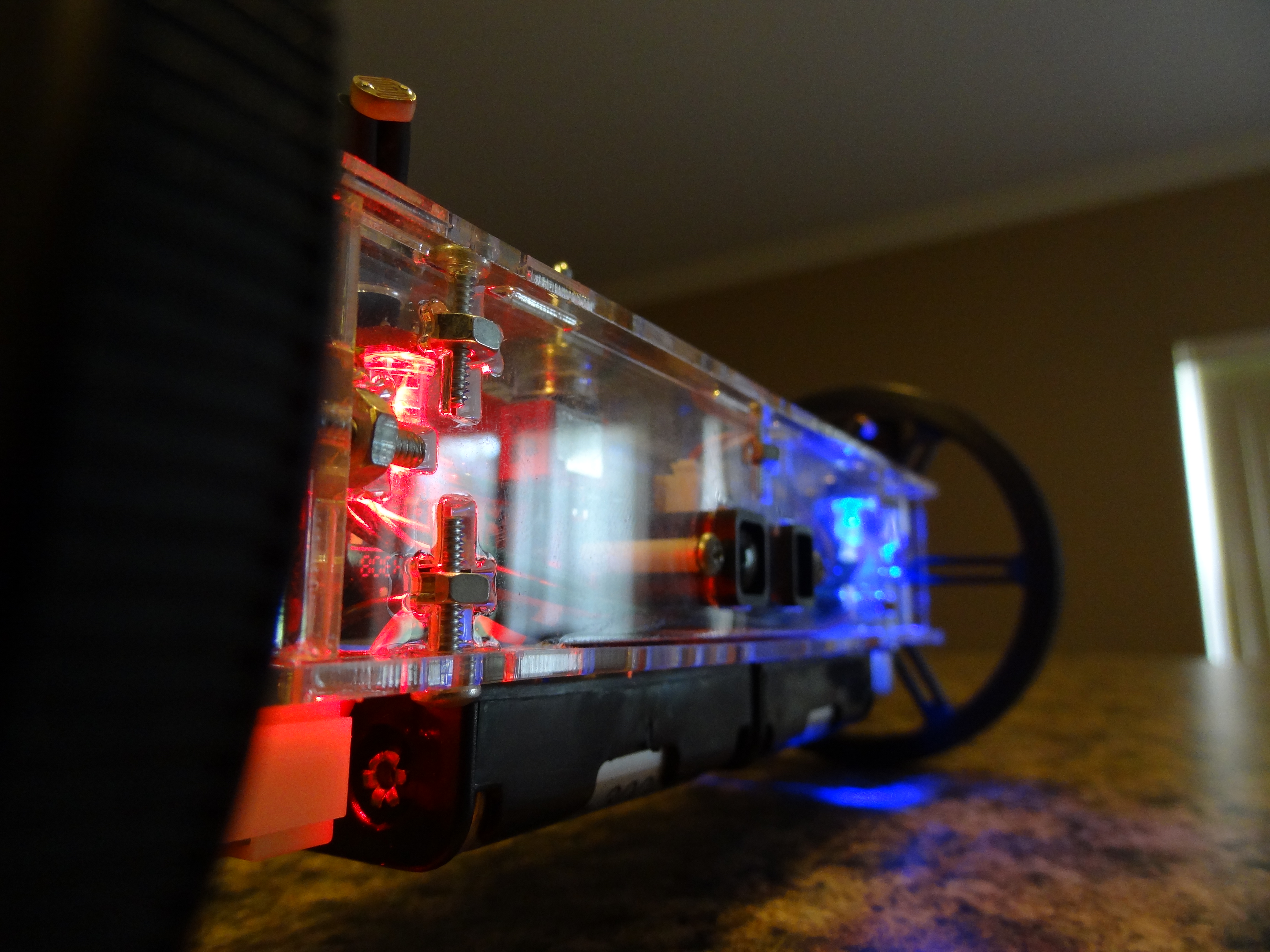
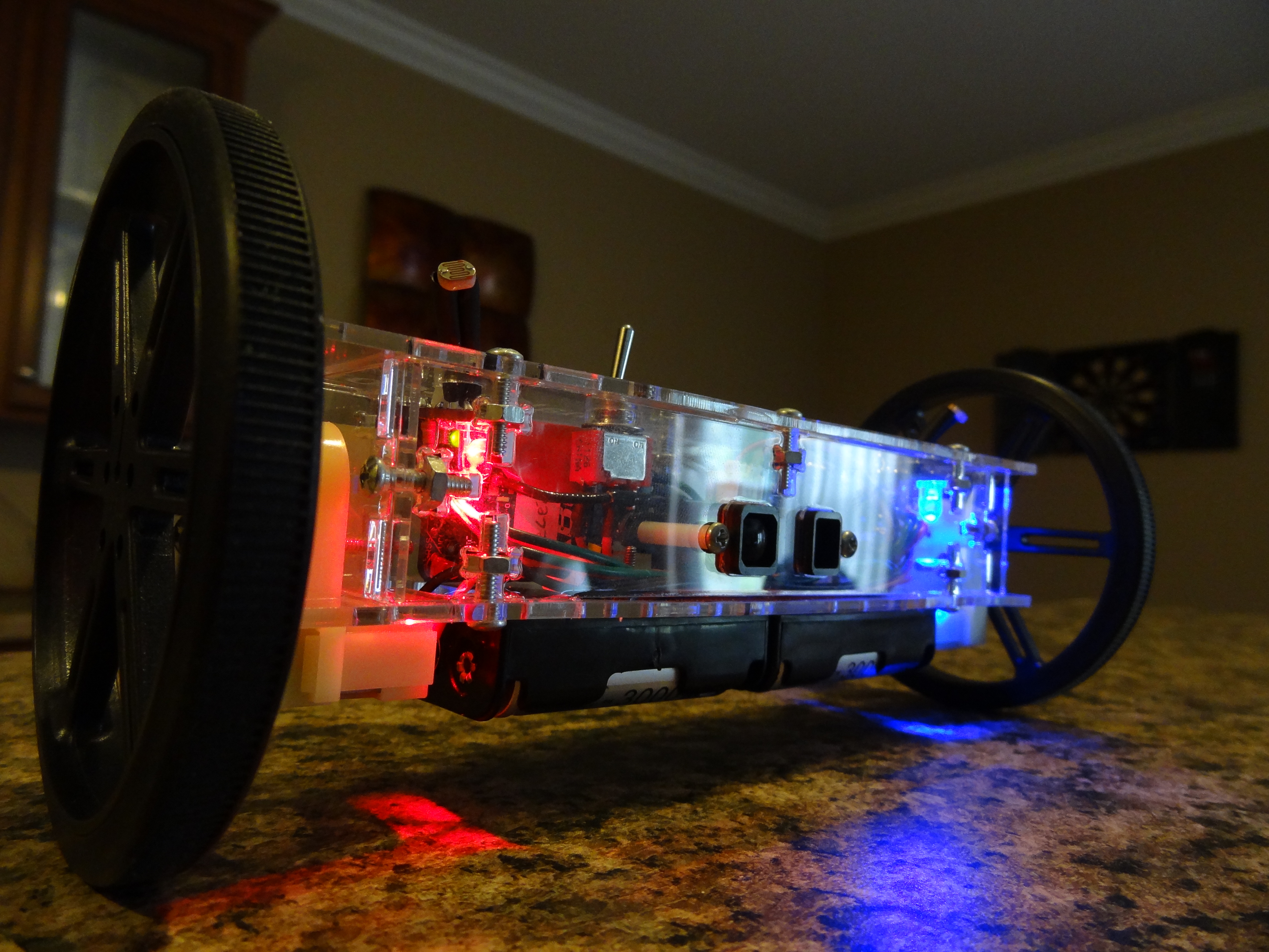
I came up with this robot just because I wanted a robot that I could easily show people. Before this one, I did not have a robot that I could really just turn on and have it demo a few different modes. I also wanted to make it a little different than most robots. I decided to go with making a robot that only had 2 contact points with the ground. The body of the robot acts like a pendulum which keeps it balanced for the most part. It is however a bit rocky, which hints the name. It has a distance sensor for object avoidance, 2 light sensors for light seeking, and a Xbee transceiver for remote control using my Custom Controller I made.
Chassis Design
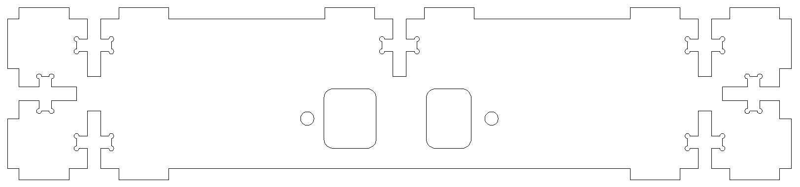
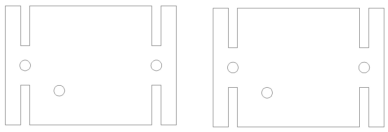
I designed the chassis in AutoCAD and cut it out on acrylic using my school’s laser cutter. The pieces fit together using notches I incorporated into the design. Bolts secure the pieces in place. (Click here to download the AutoCAD file)
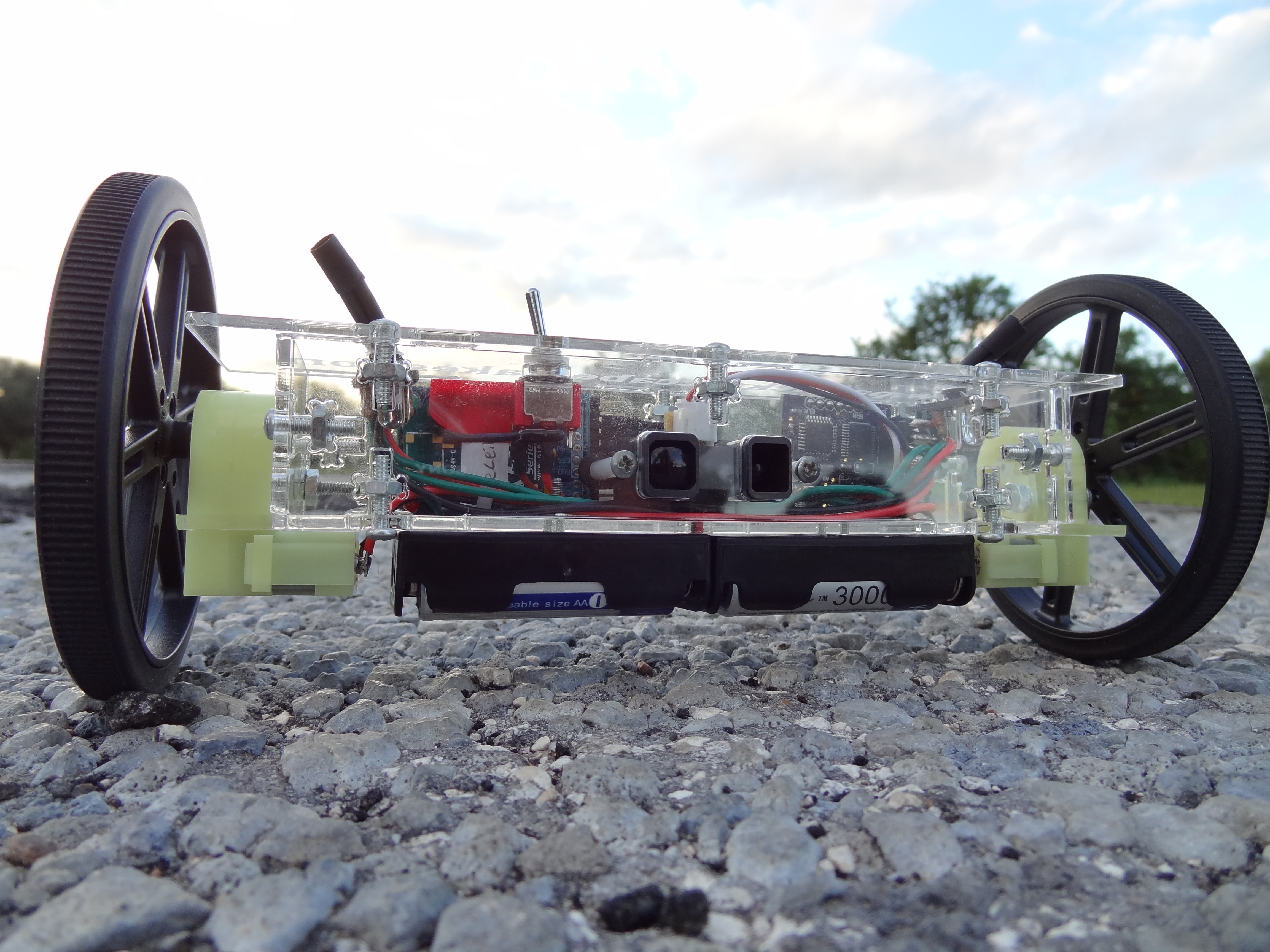
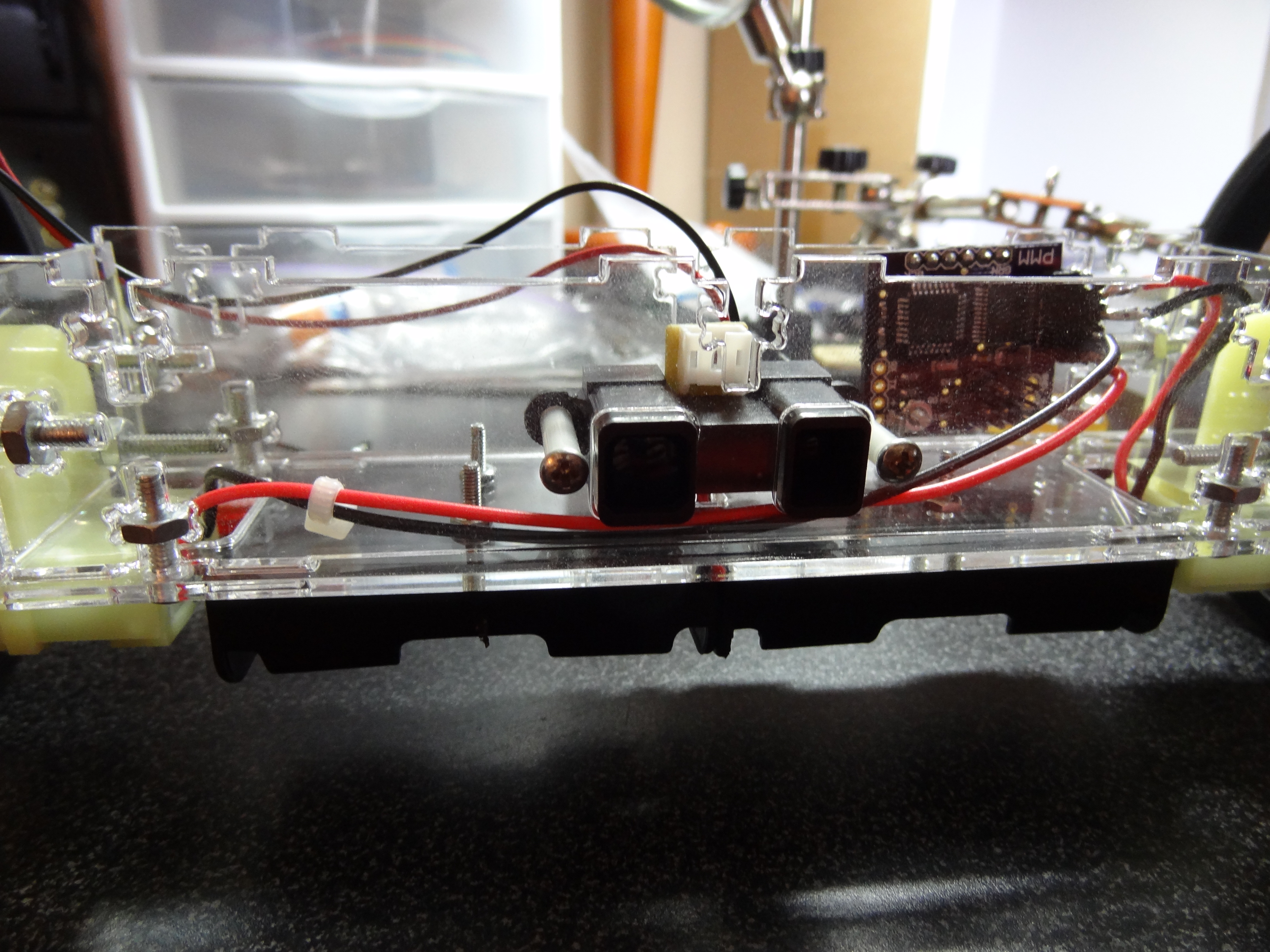
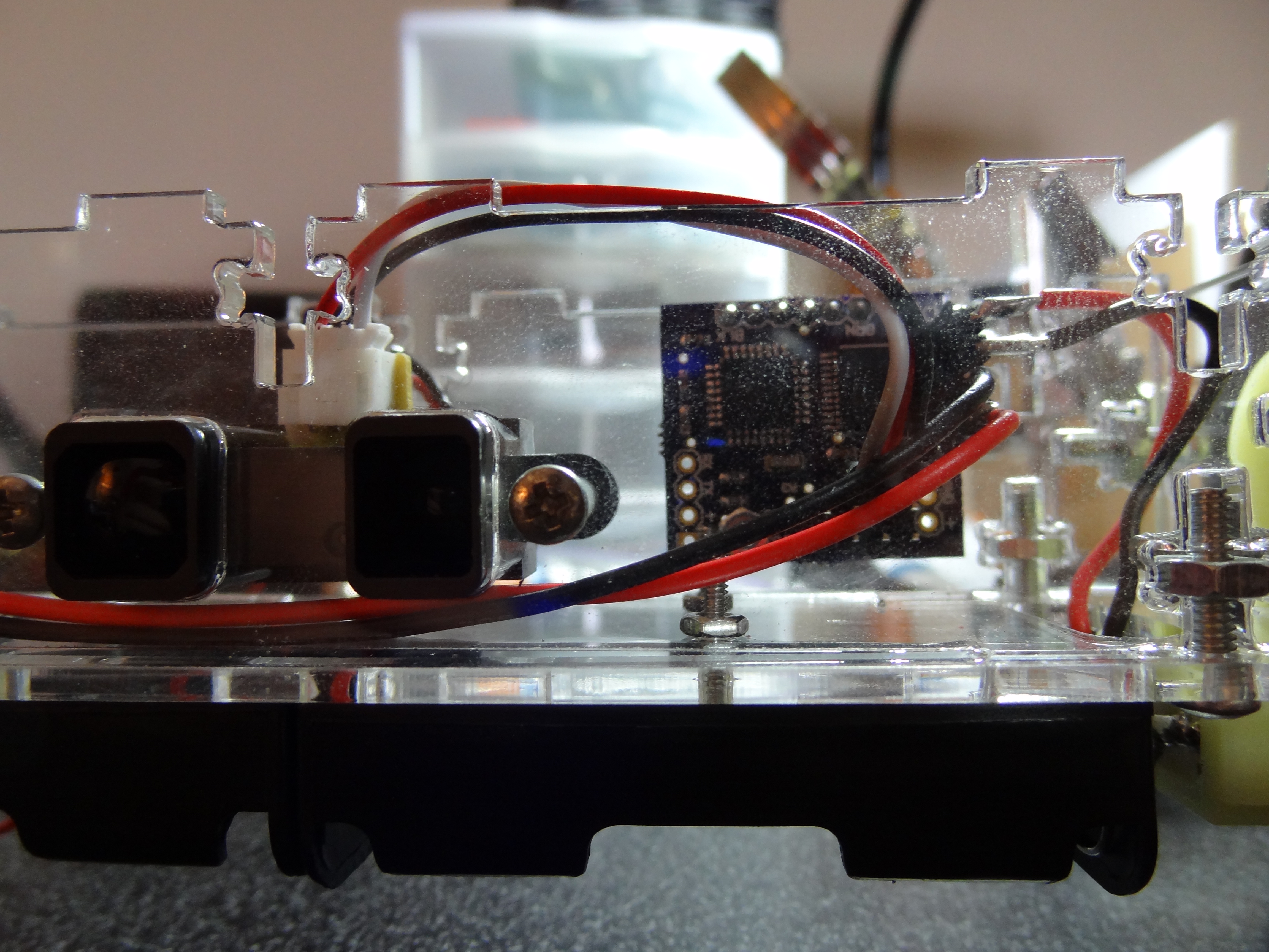
The front piece has cutouts for a long range Sharp IR distance sensor which has a range of 8”-60”. The sensor bolts onto the inside of the robot and the only parts exposed are the IR emitter and detector.
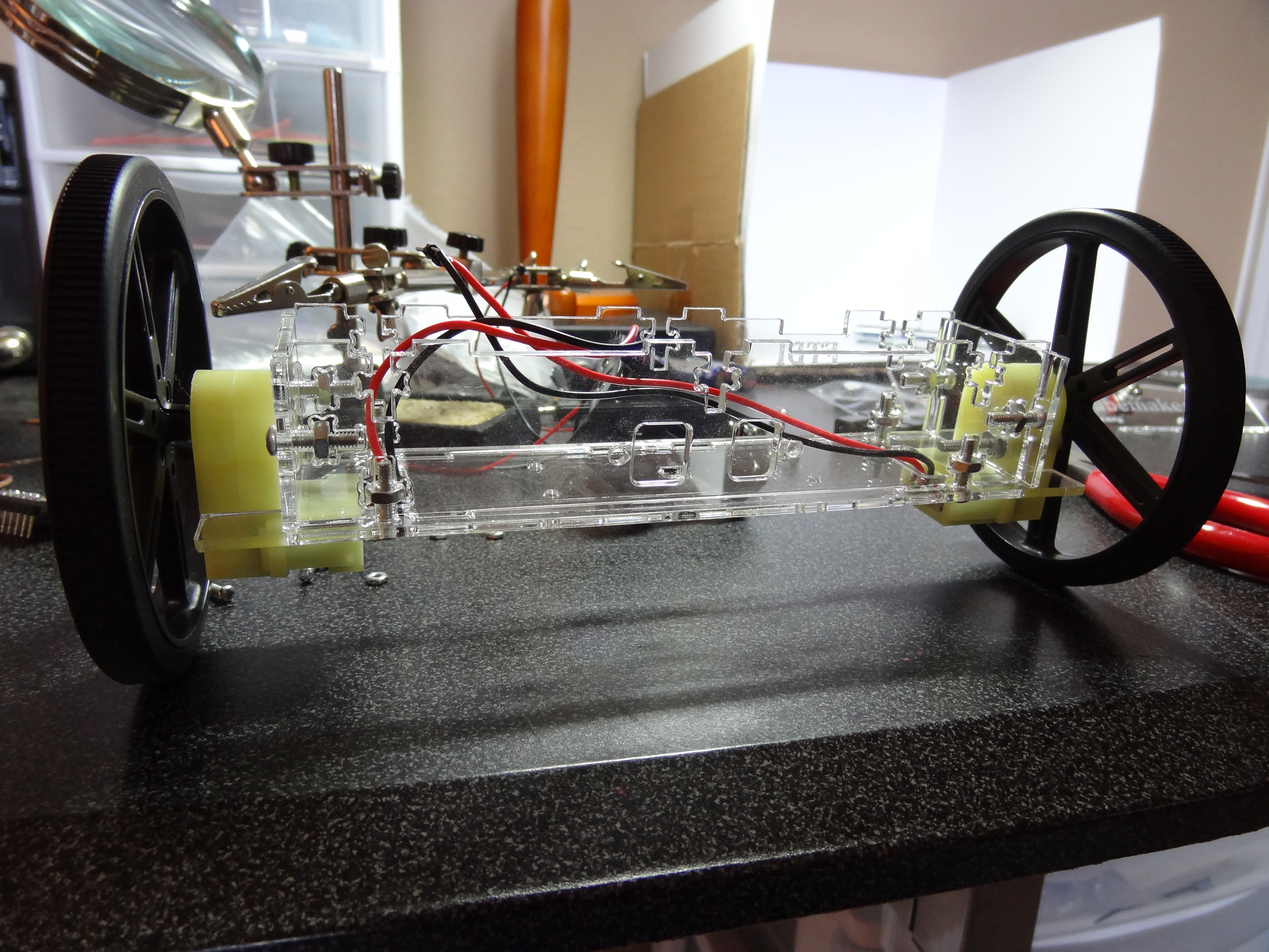
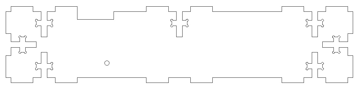
The side pieces have holes in them which allow the gear motors to bolt onto the chassis. I chose the biggest wheels (90mm D) that I could for these motors because that would give me the most space to design within. The robot has to be able to fit within the diameter of the wheels. I originally wanted to use one of these micro gear motors, but they were just too expensive and I did not need anything that small.
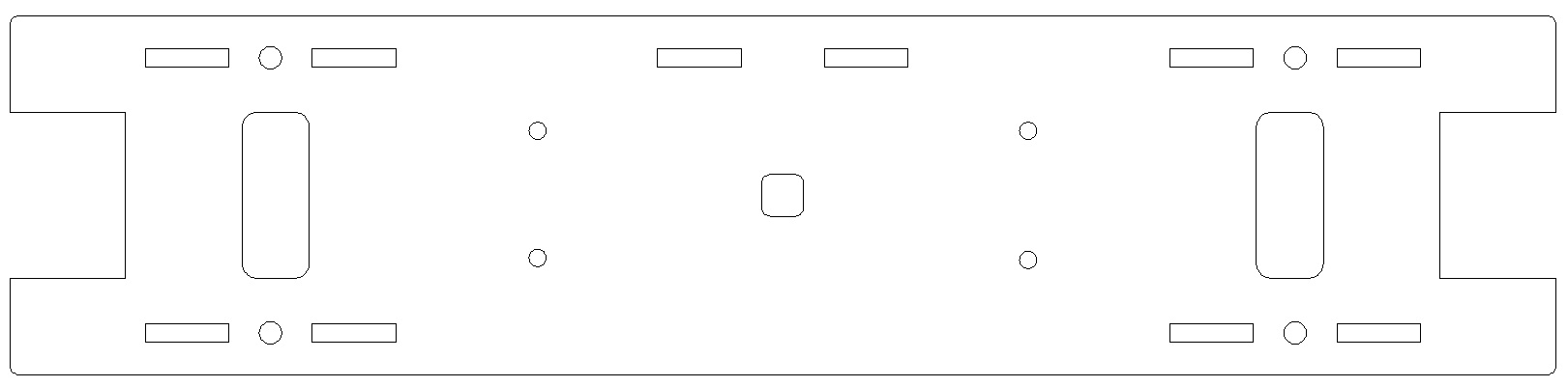
The bottom plate has mounting holes for two 2-AA battery holders. There is a hole in the center that allows the wires from those battery holders to go inside the chassis to provide power to electronics. The two rectangular cutouts on the ends allow the motors to slip in and essentially wedges the motors in place. The rectangular holes on the left and right sides allows the wires from the motor to go inside the chassis and to the motor controller.
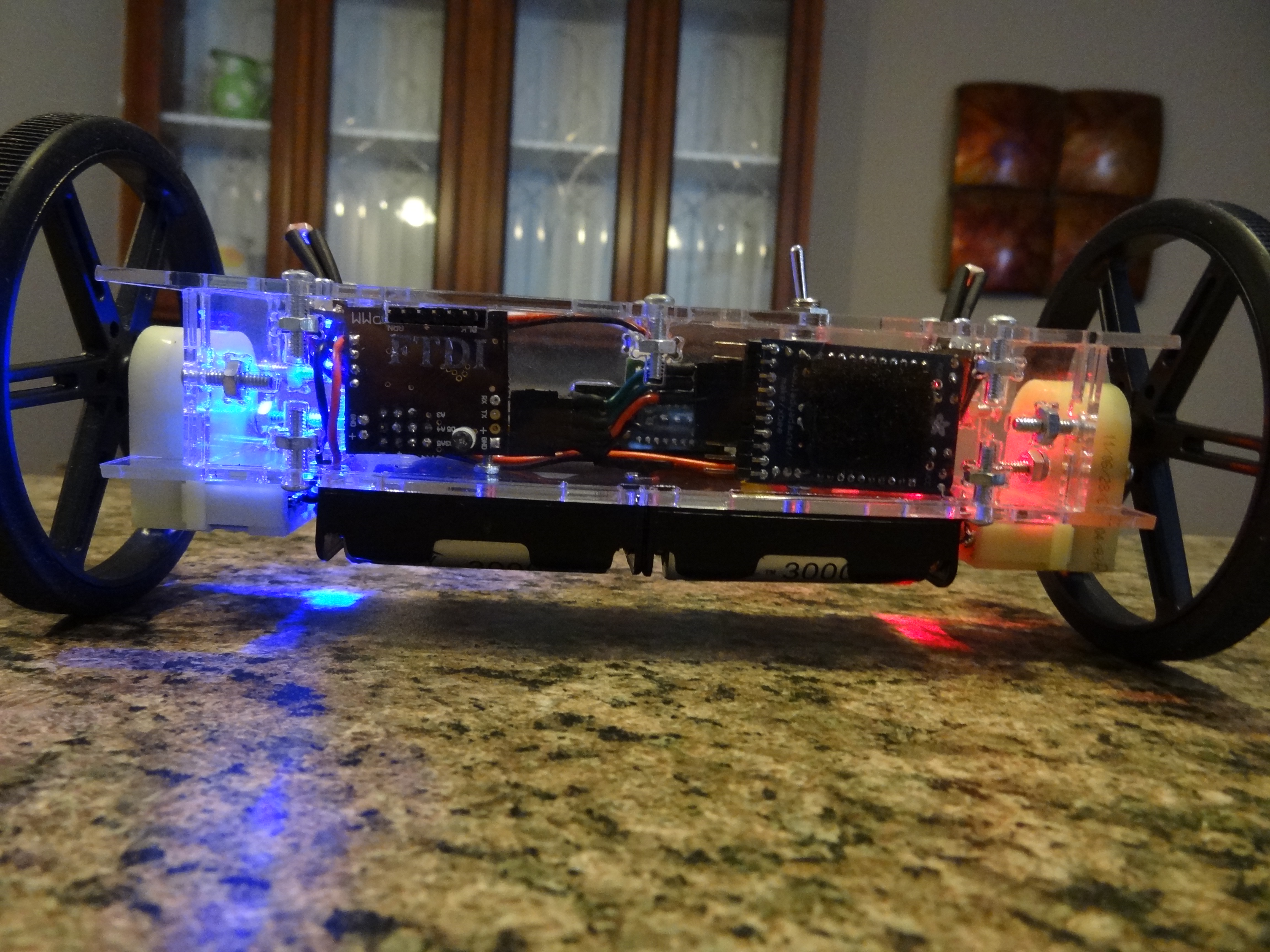
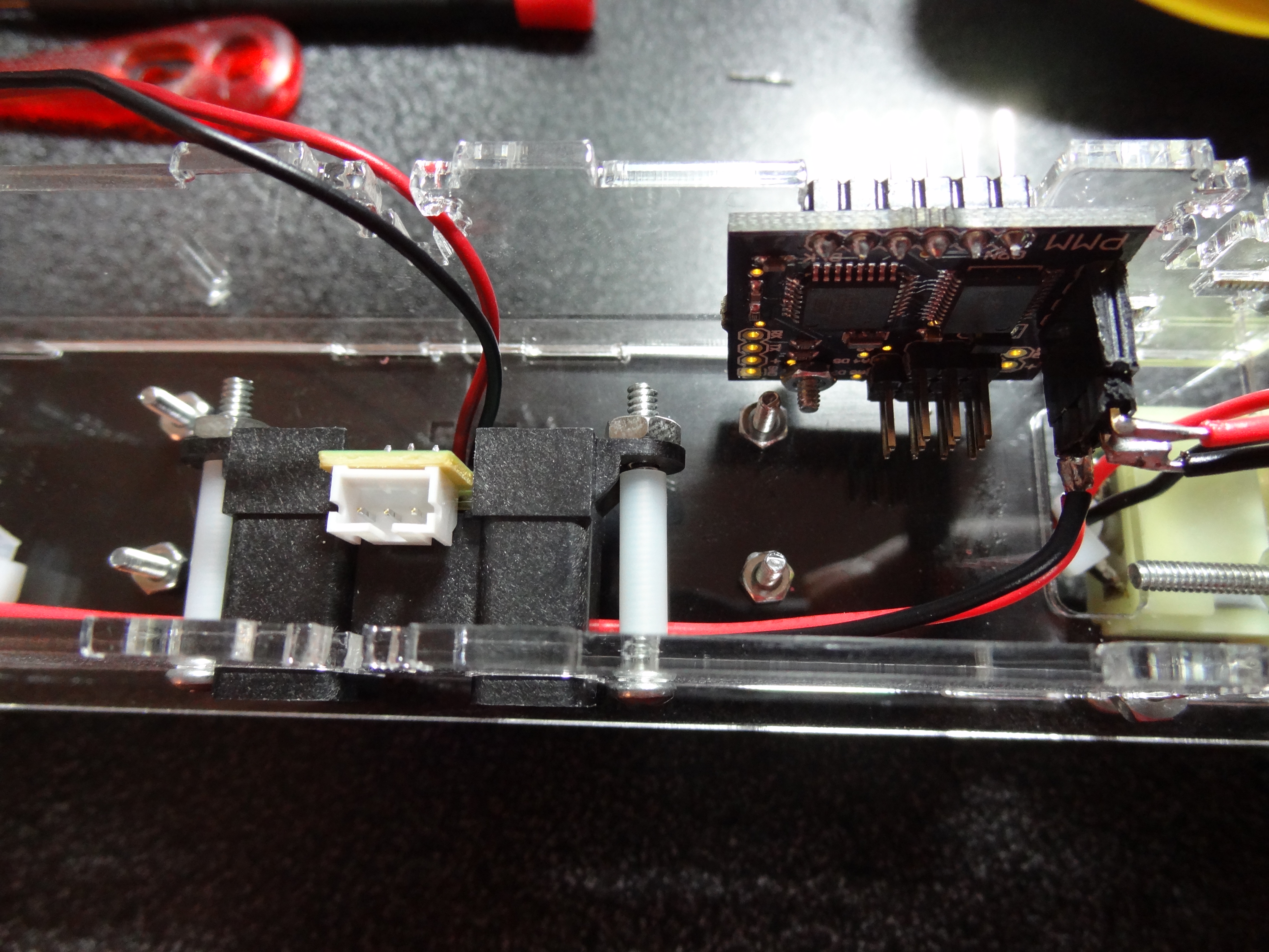
The back plate has a hole for mounting the micro-controller board on the inside of the chassis. There is also a notch above this hole which allows the FTDI programming port to stick through so the robot can easily be reprogrammed. I will cover more about the micro-controller board later in the post.
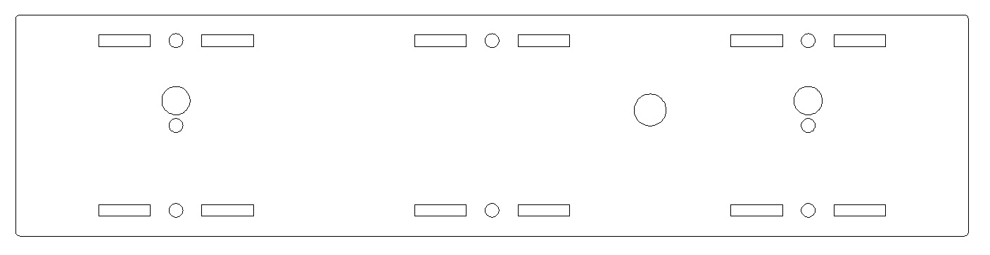
The top plate has a mounting hole for the toggle switch (the hole nearest to the center). There are 2 pairs of holes on the left and right for mounting a light sensor / LED board I designed.
Circuit Design and Construction
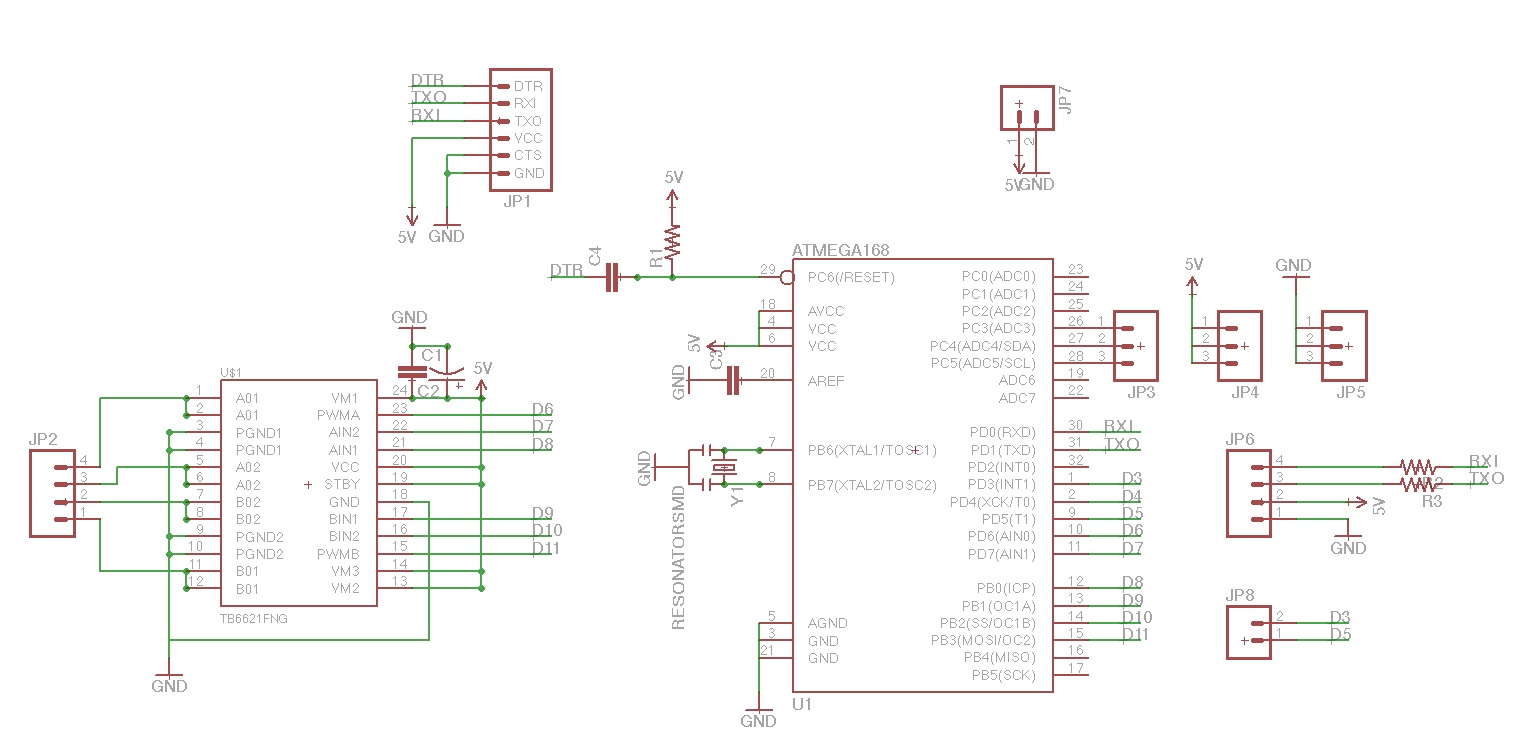
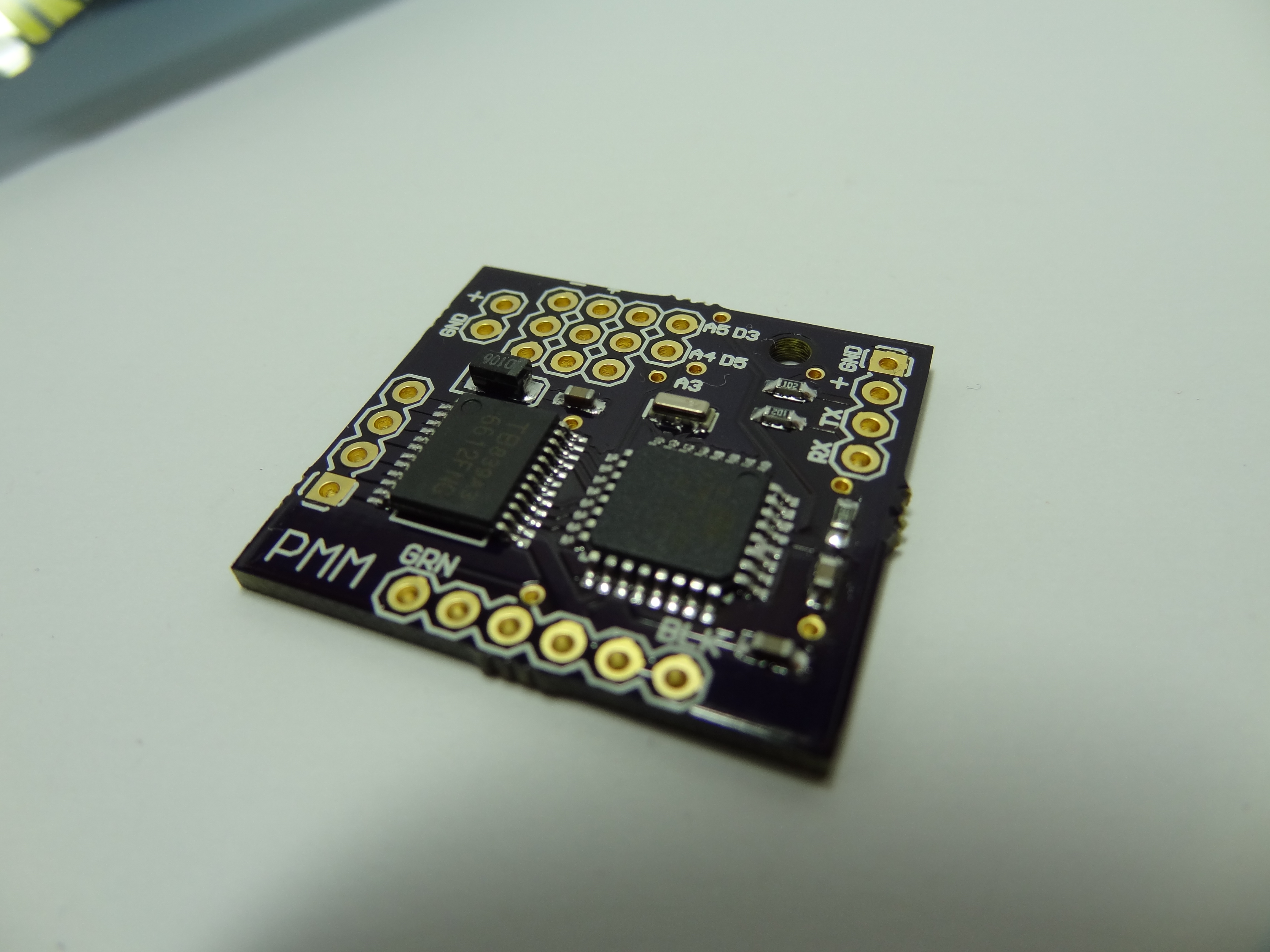
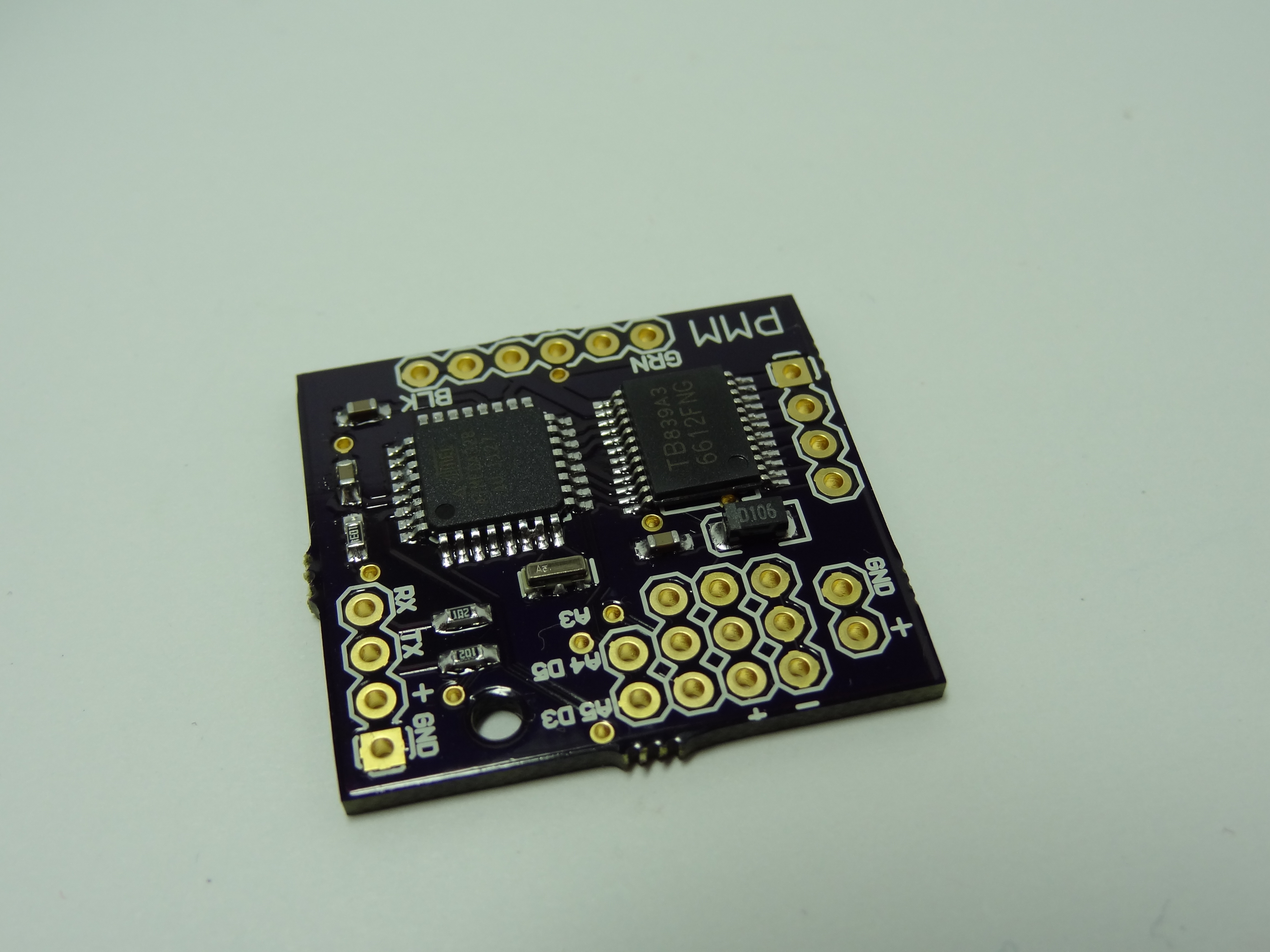
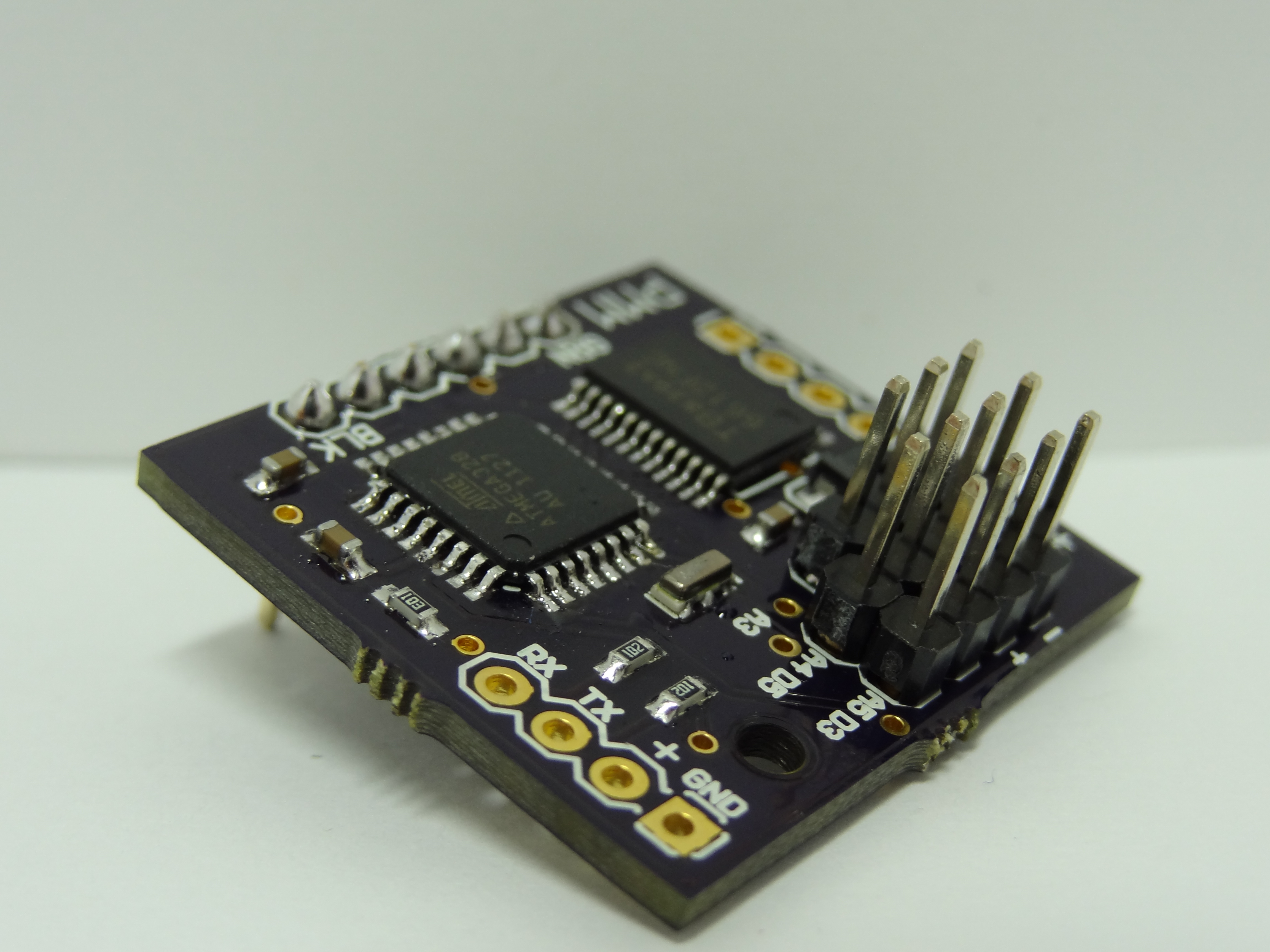
I designed the micro-controller board in EagleCAD (download Eagle files). It has an Atmega-328 surface mount micro-controller with the Arduino bootloader on it. The motors are controlled using a 1.2A TB6612FNG surface mount motor driver IC. This motor driver allows for direction and speed control of the motors by using the digital I/O of the Atmega-328 and connecting the enable pins to PWM capable pins. The board also has 3 analog inputs, 2 digital I/Os (I use them for PWM control of the onboard LEDs), and a serial port for wireless communication using a Xbee transceiver.
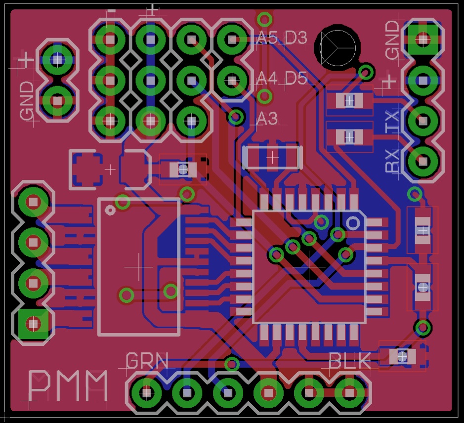
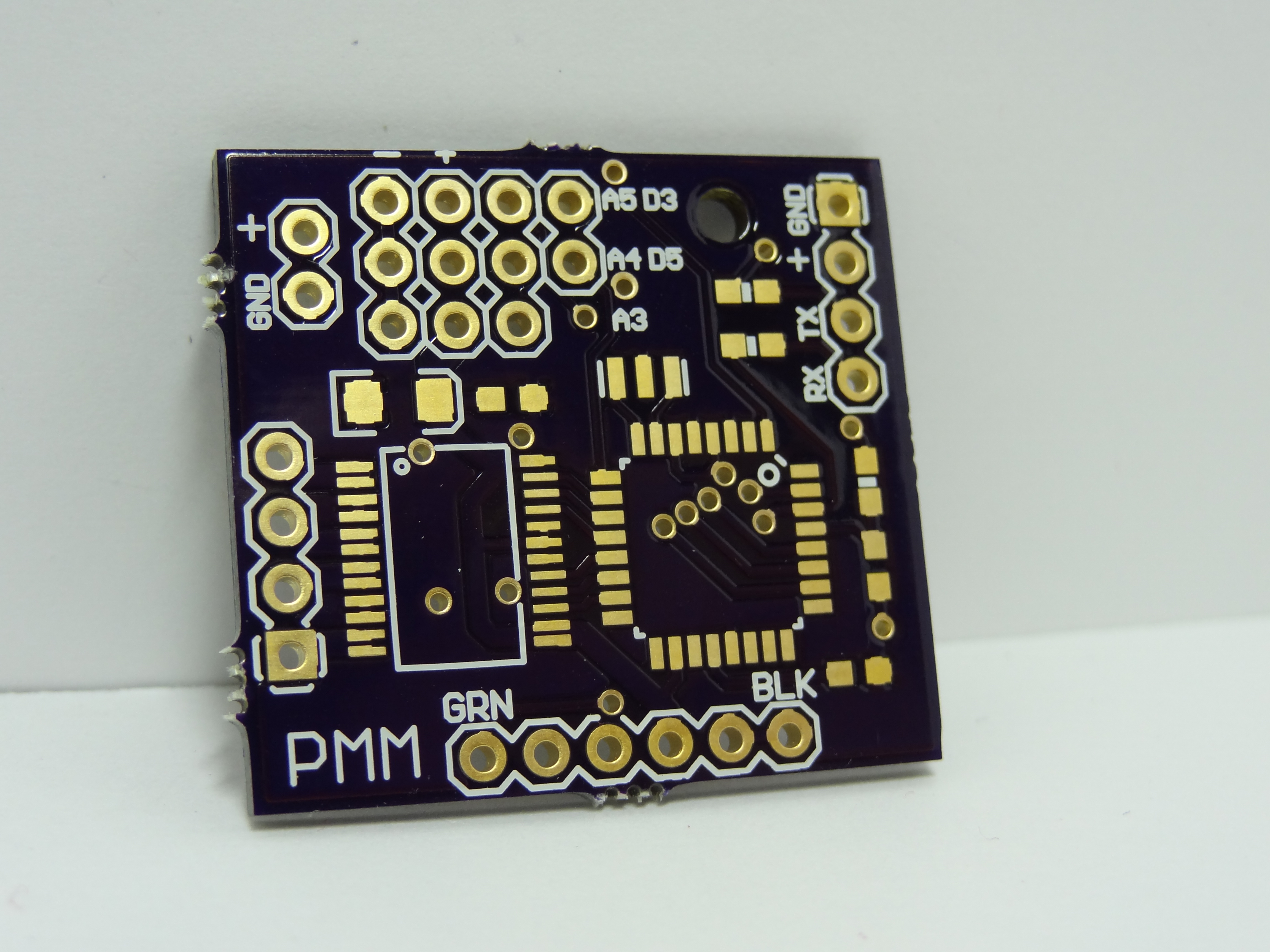
I had the PCBs made by dorkbotPDX (now called OSHPark).
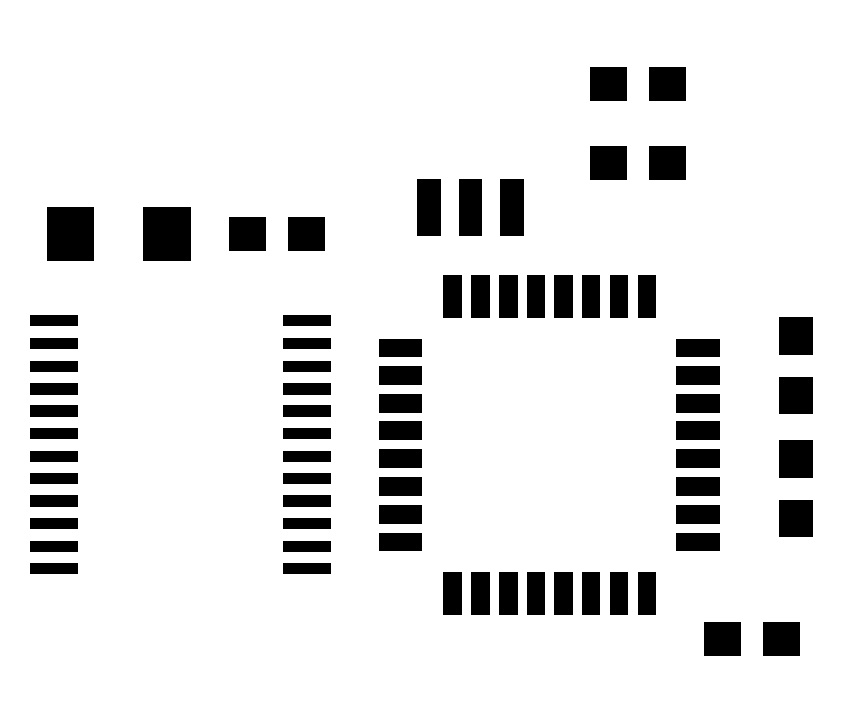
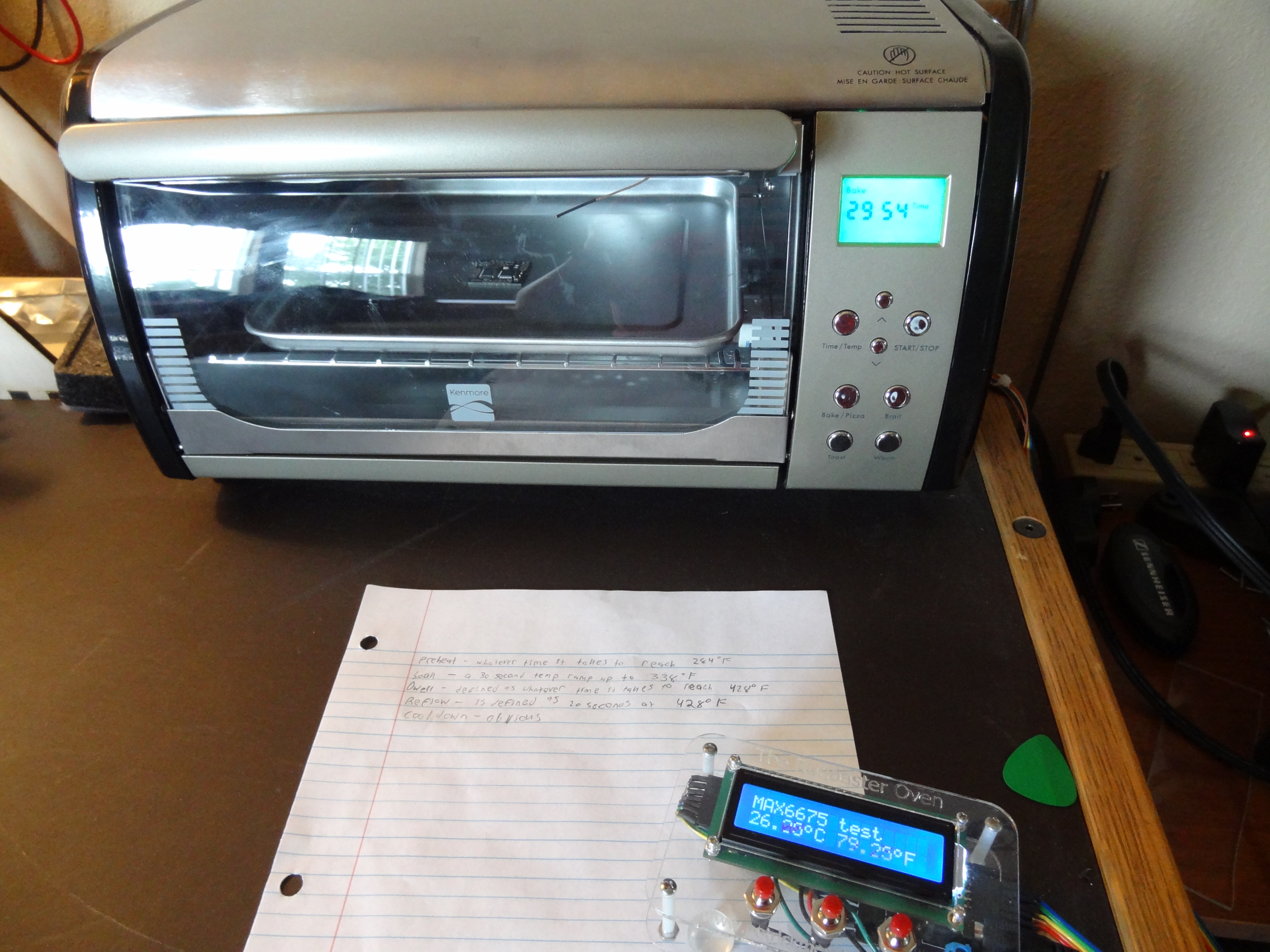
I wanted to assemble the board using my Refloaster Oven. To do this, I created a solder stencil for applying solder paste to the board. This solder stencil is made from a 35 cent plastic report cover for like turning in research papers. I followed the adafruit tutorial on how to laser cut a solder stencil. I used my school’s laser cutter to create this. To hold the plastic in place, I taped the sheets on a piece of glass.
Here is whate the PDF that I created from the PCB files looked like (download PDF stencil):
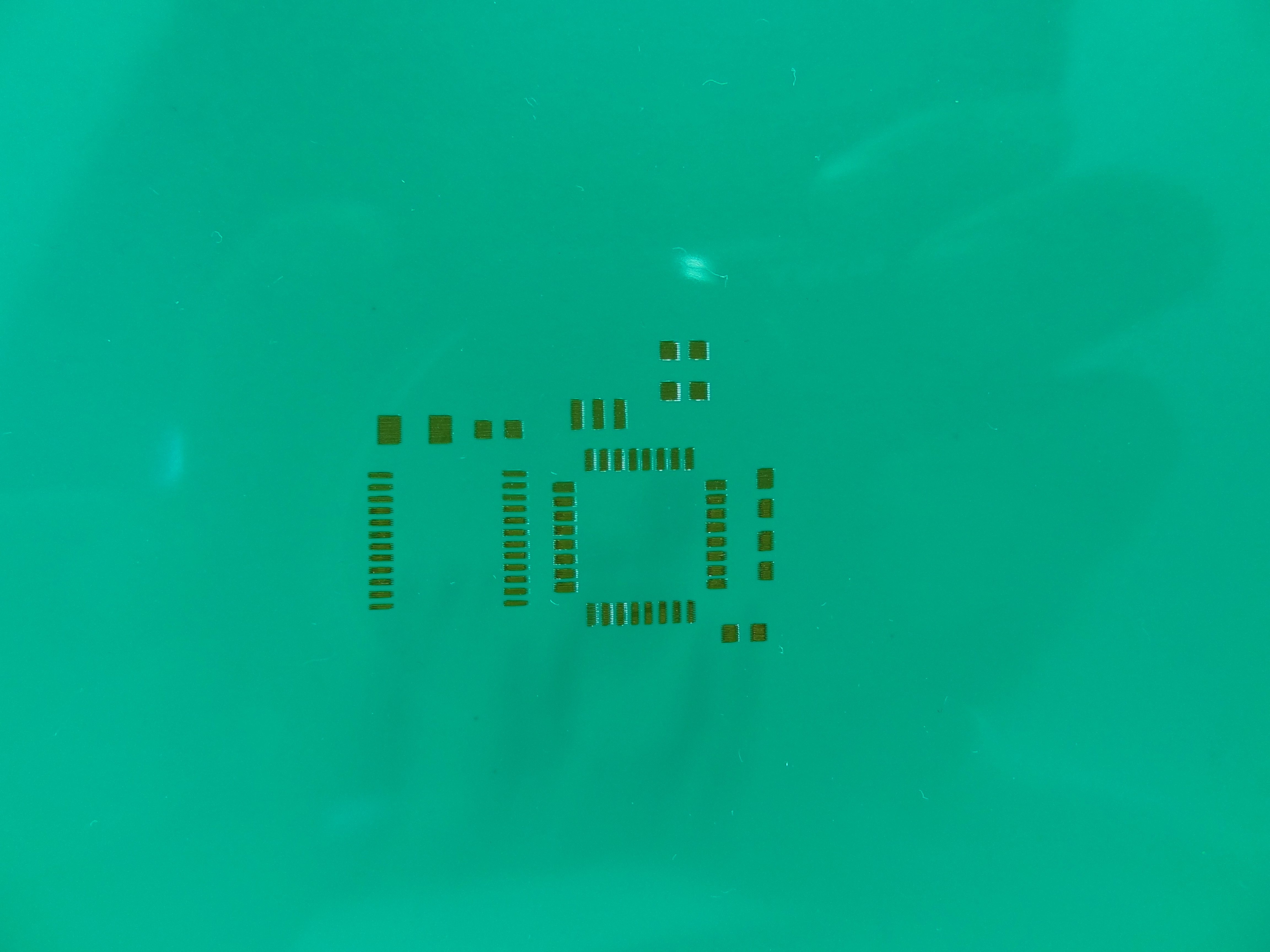
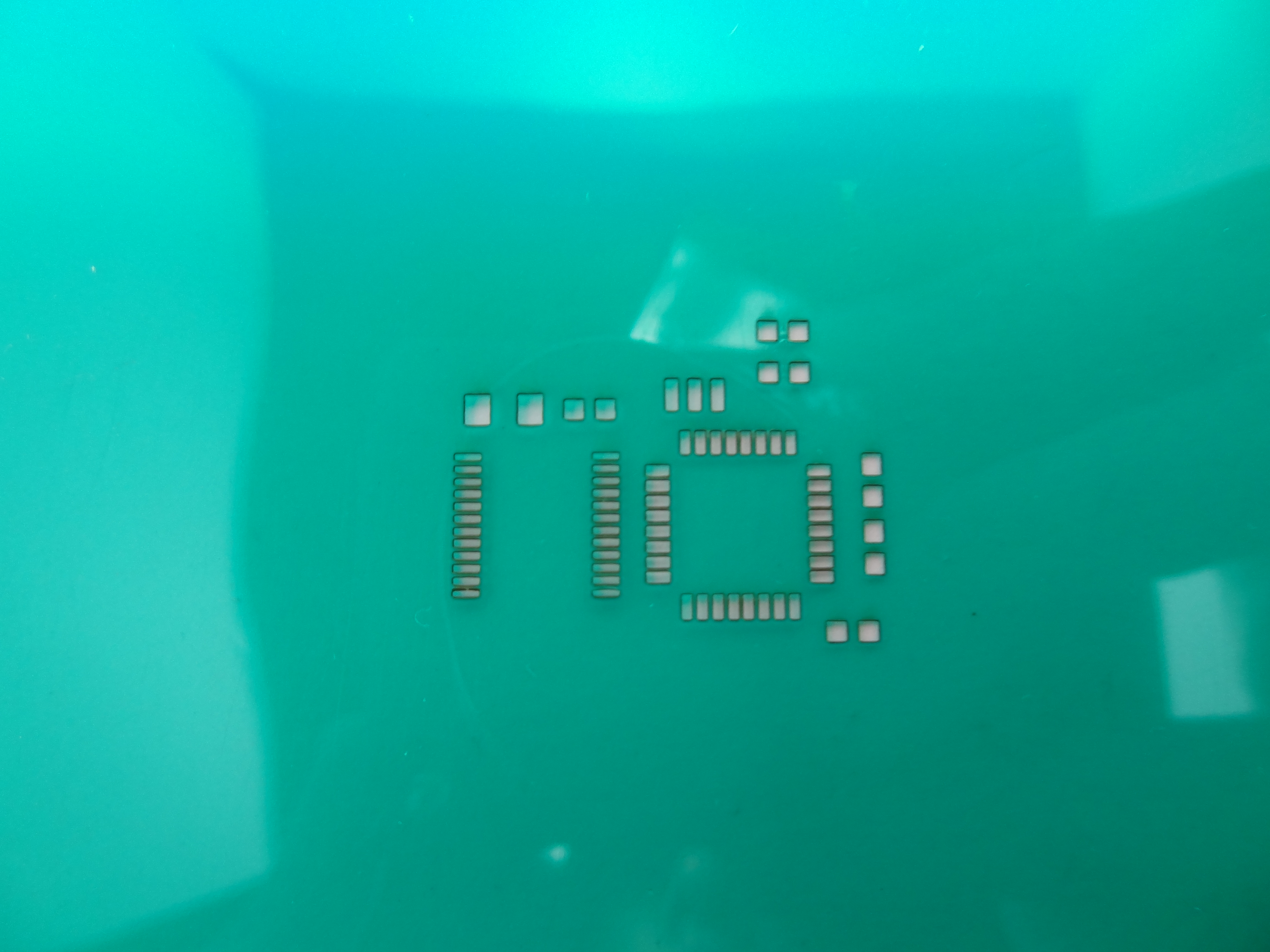
You can see my 3 different attempts at etching out the stencil below. The first attempt just barely marked the plastic as you can see in the first picture. I turned the power up for the second attempt and it completely etched the image on the plastic, but it did not actually burn through. I really increased the power the third time and, after etching out the PDF twice, I ended up with a cleanly cut stencil.
I applied the solder paste using a straight edge. I used spare PCBs as support for the stencil when applying the paste.
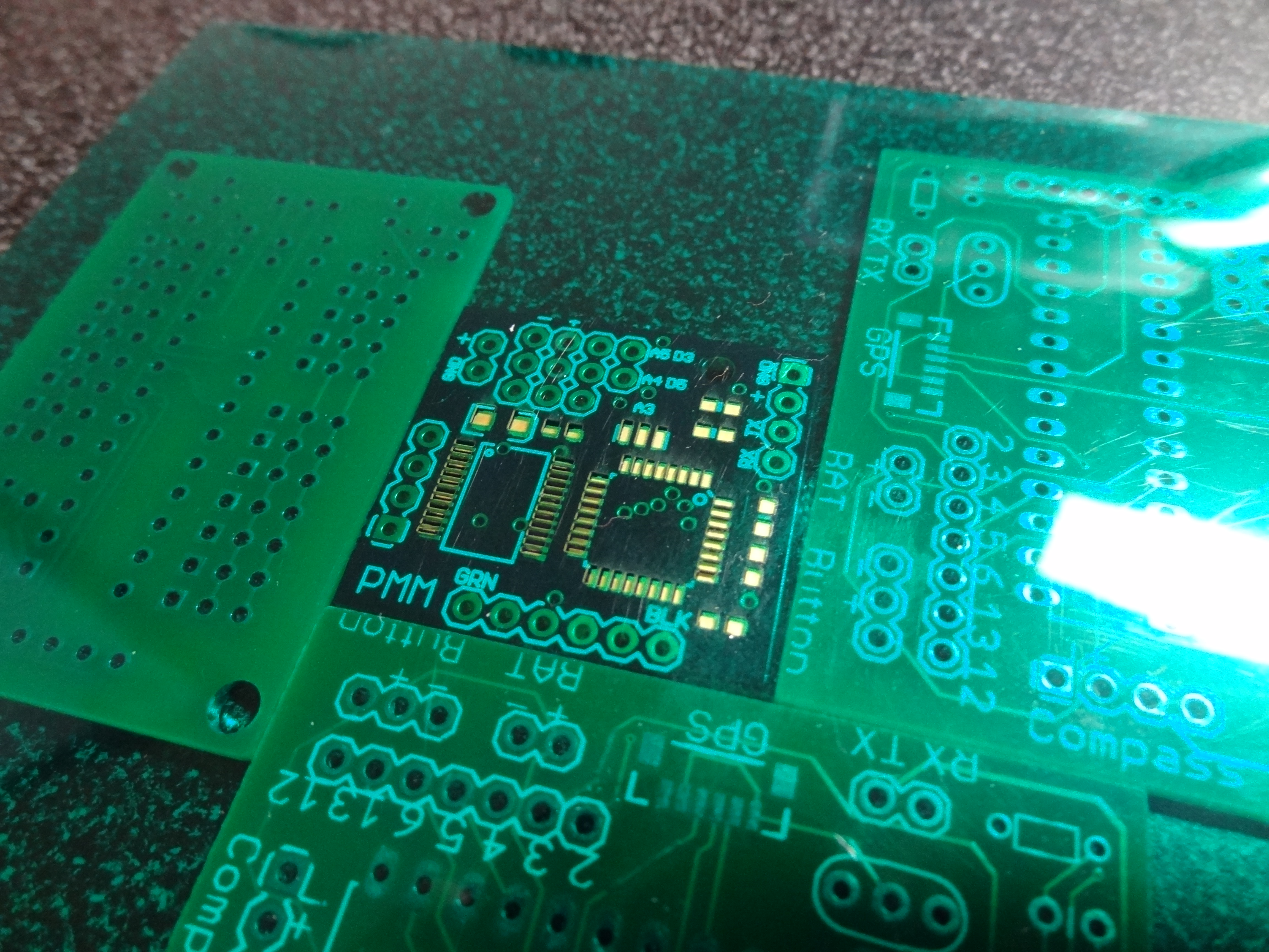
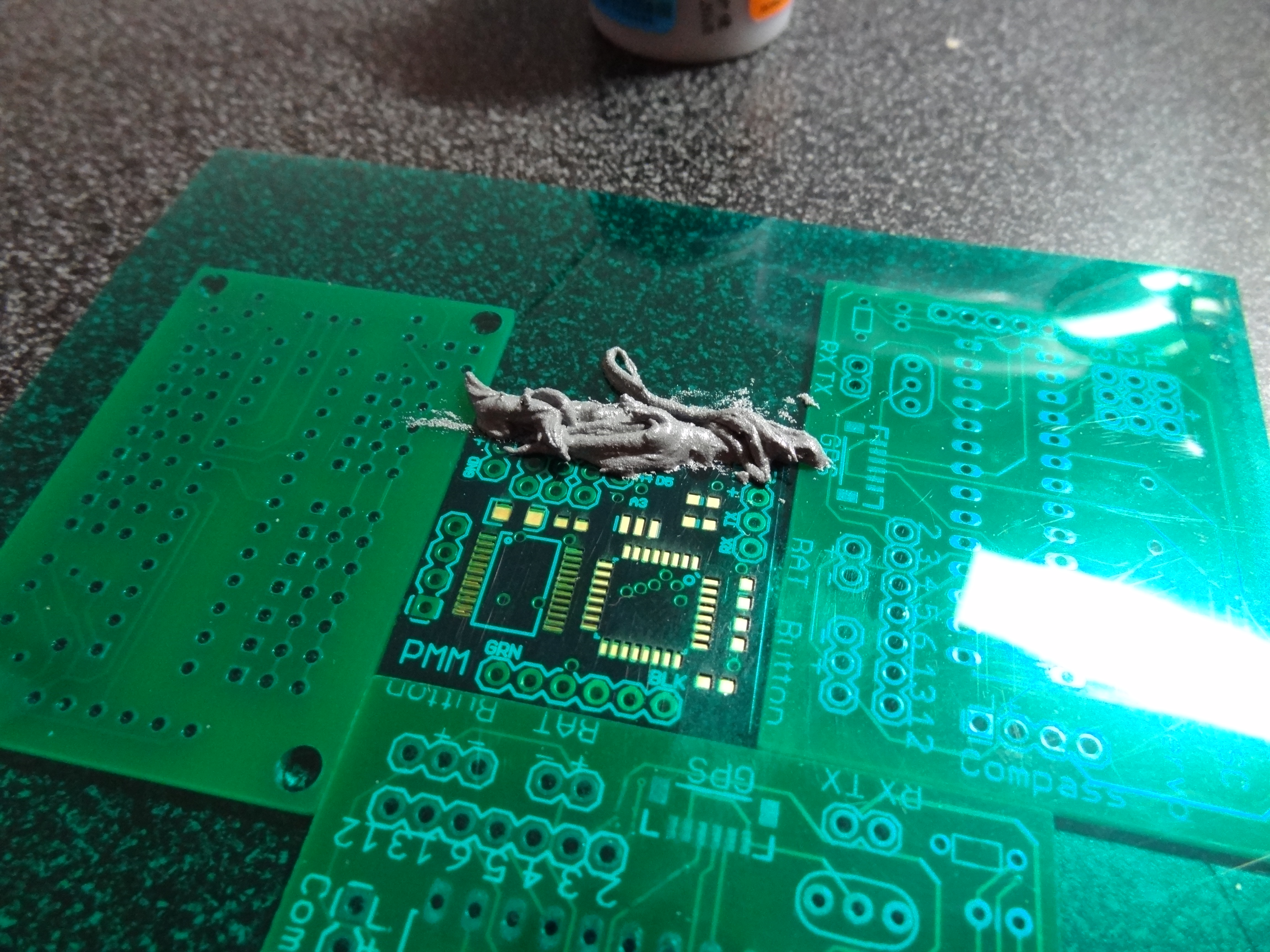
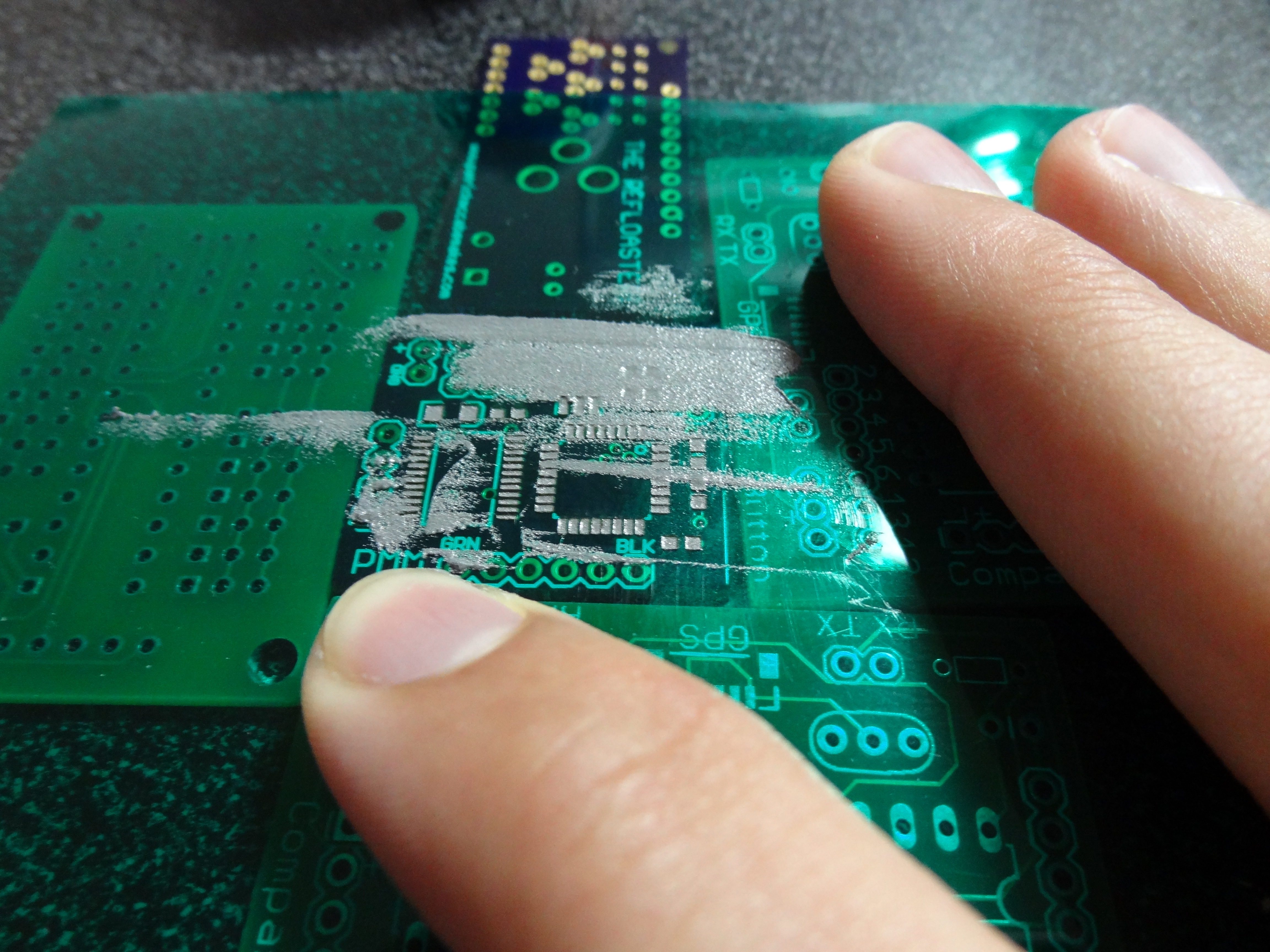
As you can see the paste is a little off on some pads. I think it came out well for my first try. Practice makes perfect, right?
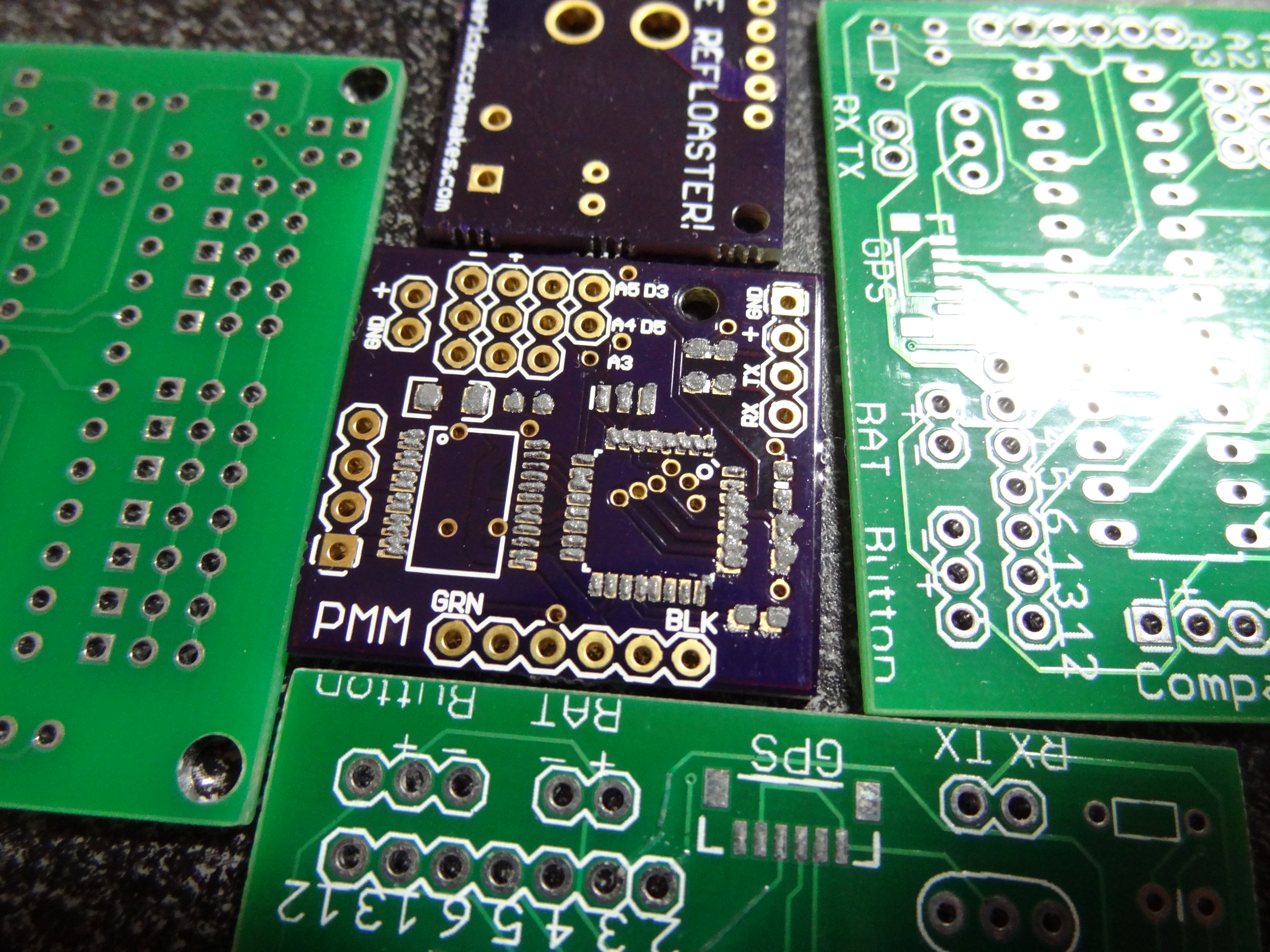
I then used my SMD tweezers to place the parts on the pads. This part is a little difficult. It takes a steady hand.
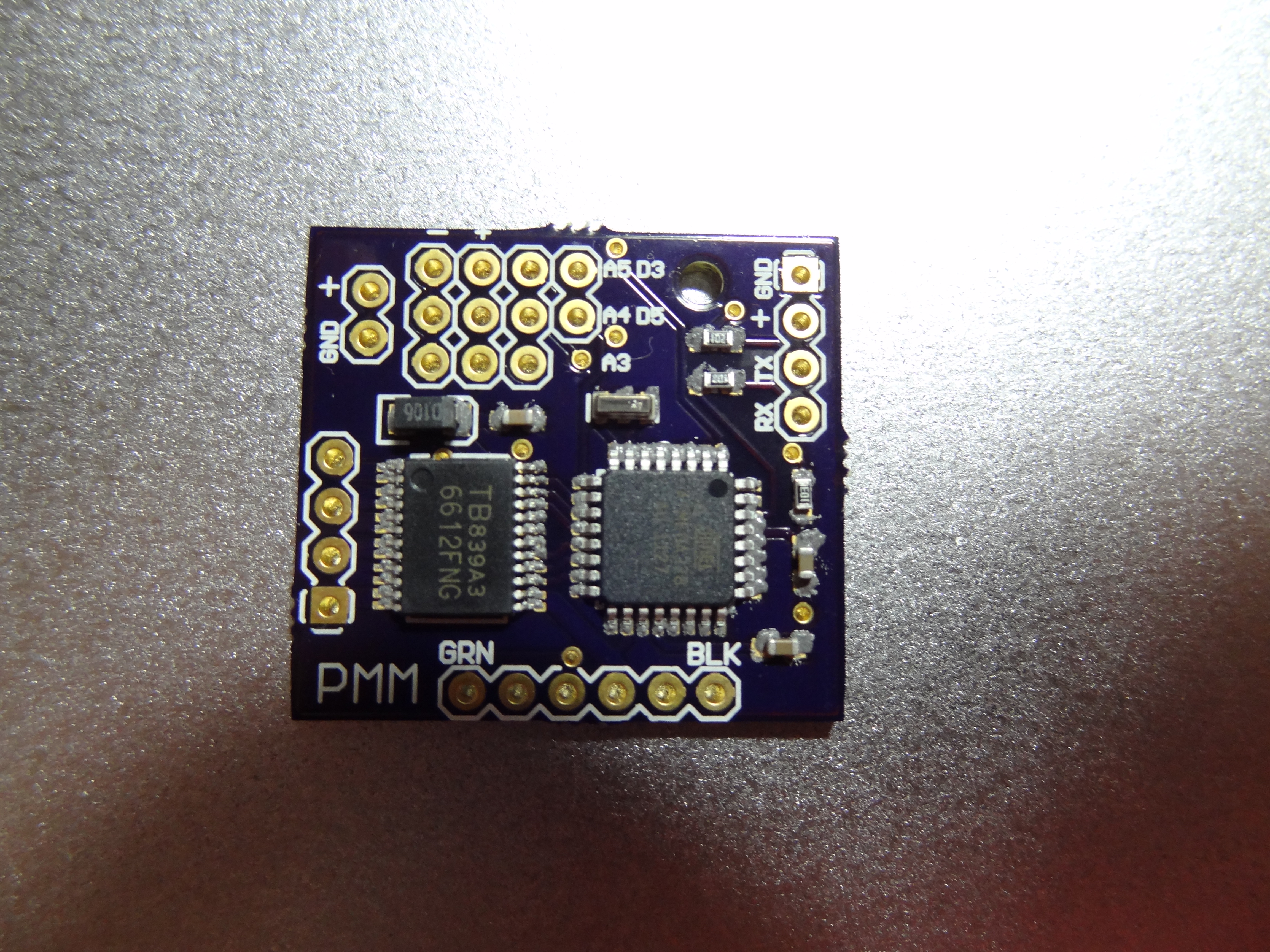
The next step was to reflow the board in the Refloaster. All I had to do was put it on a tray, turn on the oven, and wait.
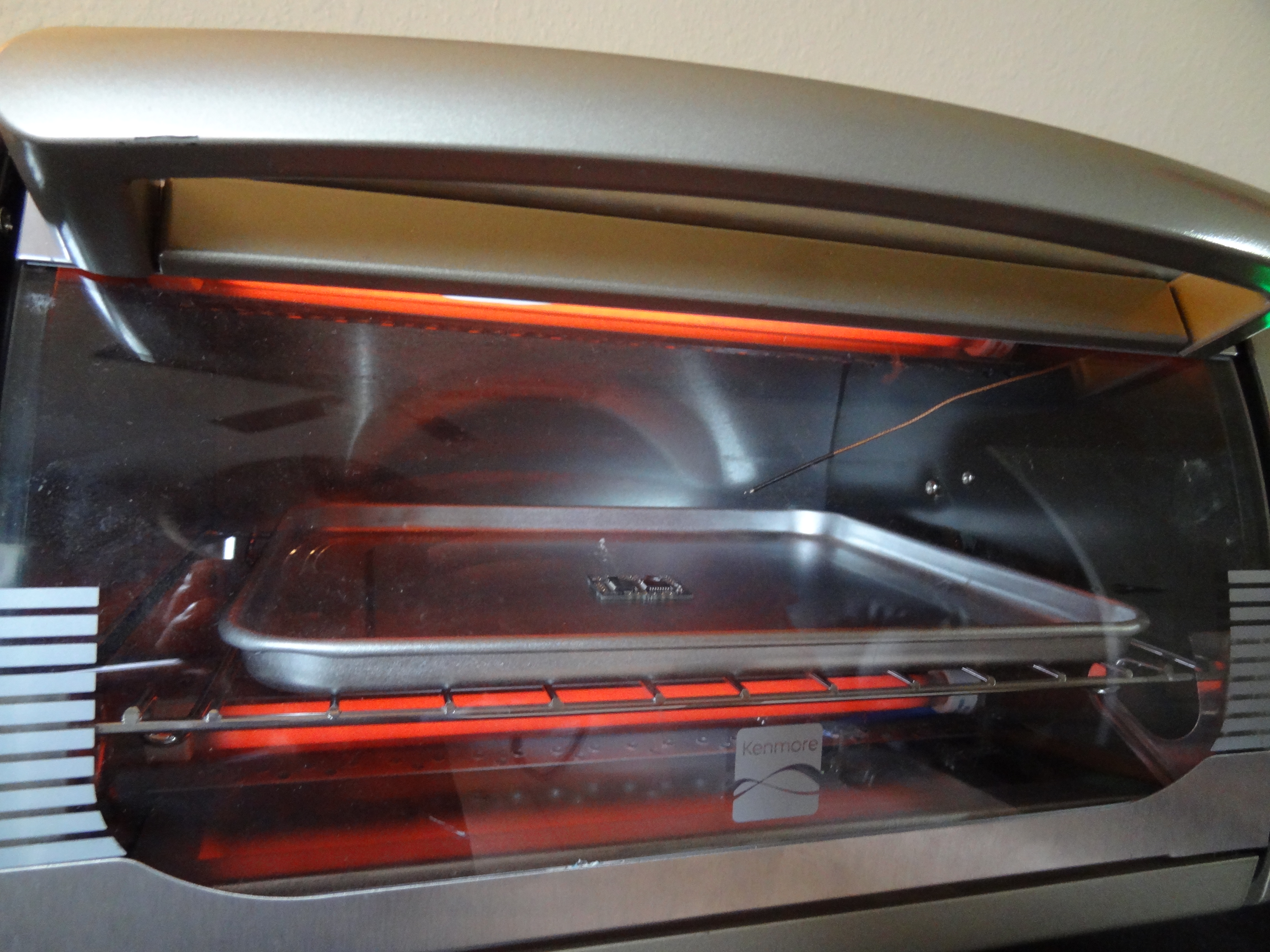
It came out pretty well. It had a few solder bridges and some pins did not get enough solder. I was able to touch this up by hand using my soldering station. I hope it gets better with more experience. This still was much easier than it would have been to hand solder it.
I then hand soldered on the some of the pin headers for the FTDI connection, the analog pins, and the digital pins.

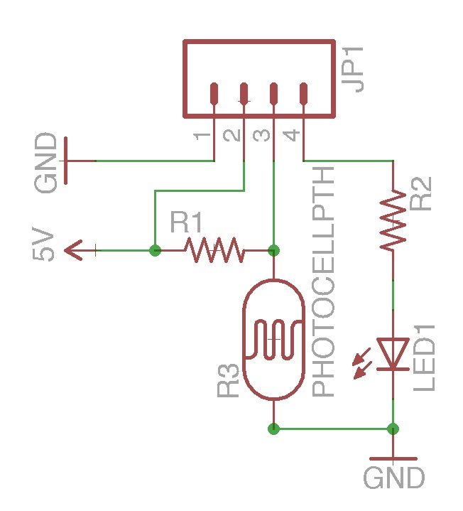
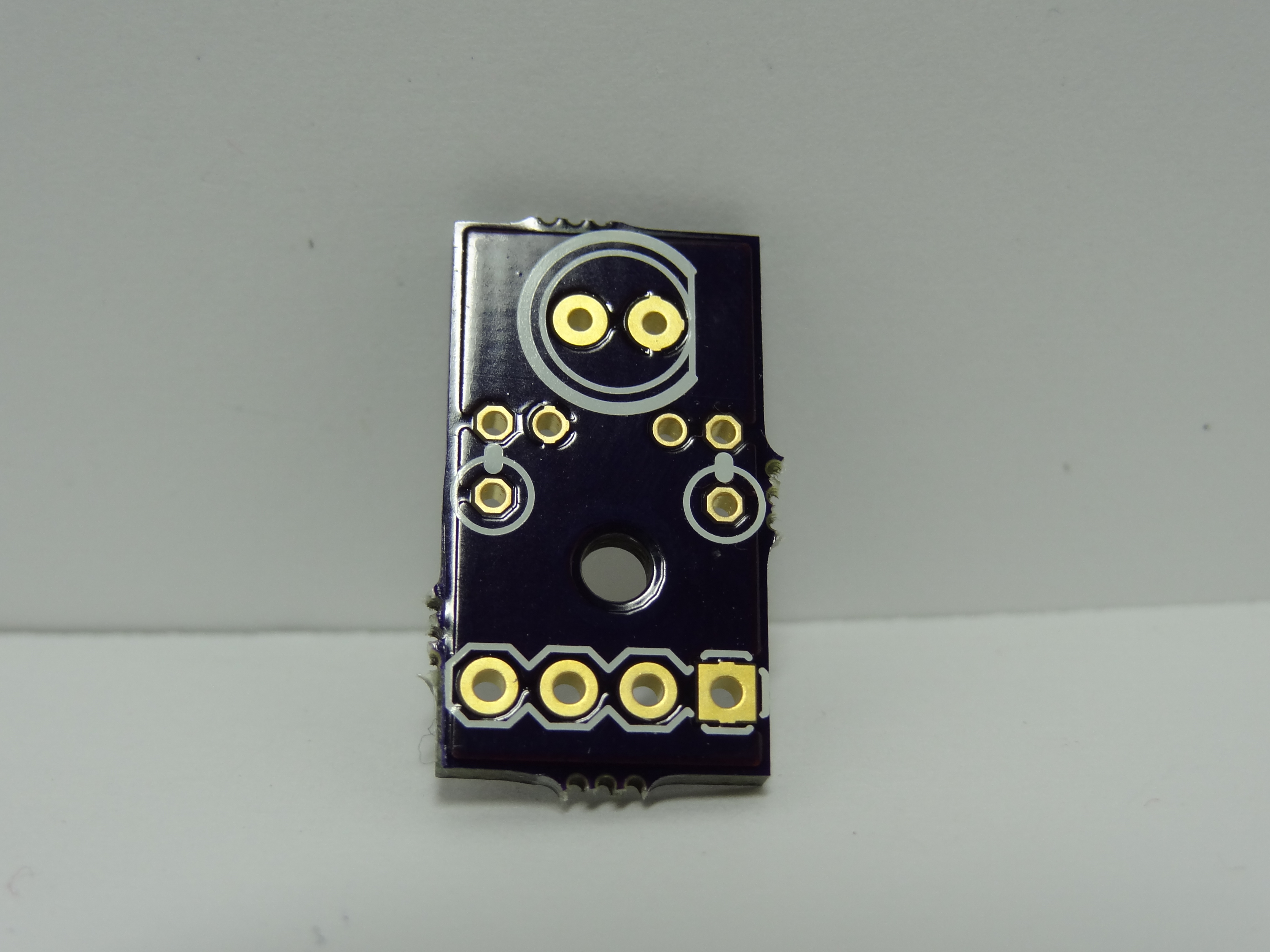
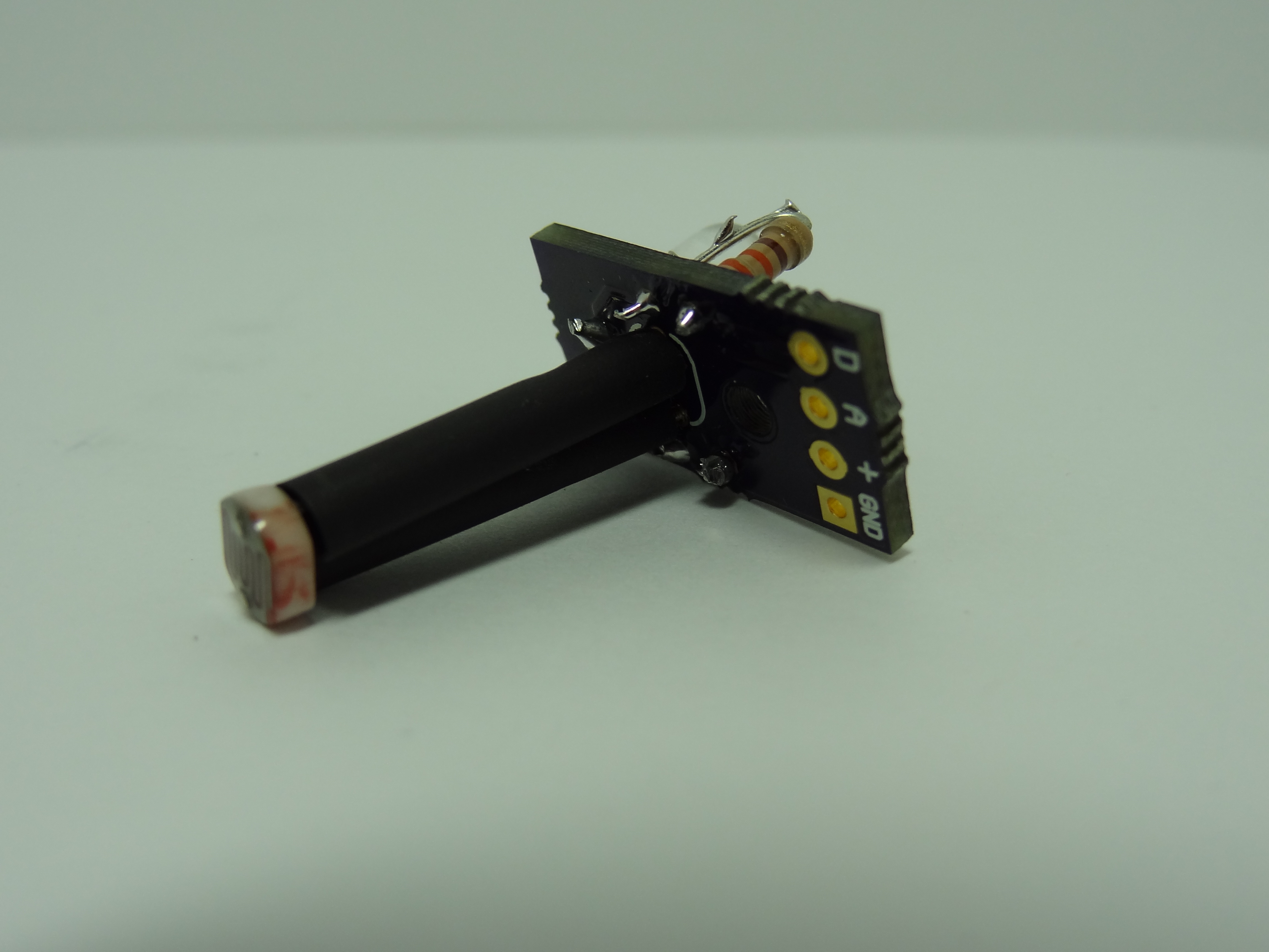
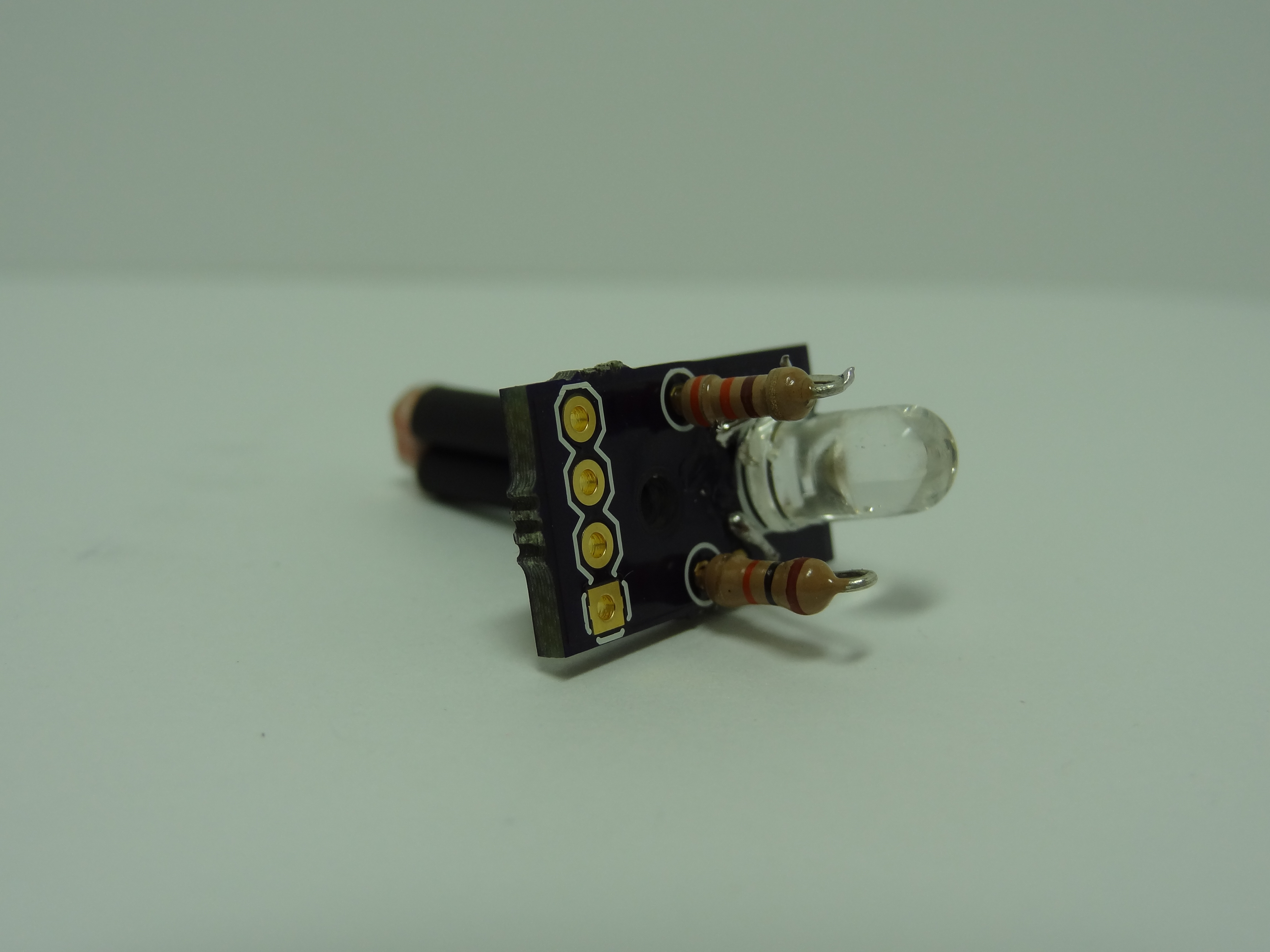
I designed a second, really simple PCB for this robot. It has a LDR (light dependent resistor) on top for sensing light levels and a 5mm LED on the bottom. It also has 2 required resistors. This board mounts to the top of the robot so that the LDR sticks out the top and the LEDs shine downwards. This gets wired directly to pinouts on the micro-controller board. (download Eagle files)

I also had these PCBs manufactured by the dorkbotPDX service. You can also see the module soldered together below.

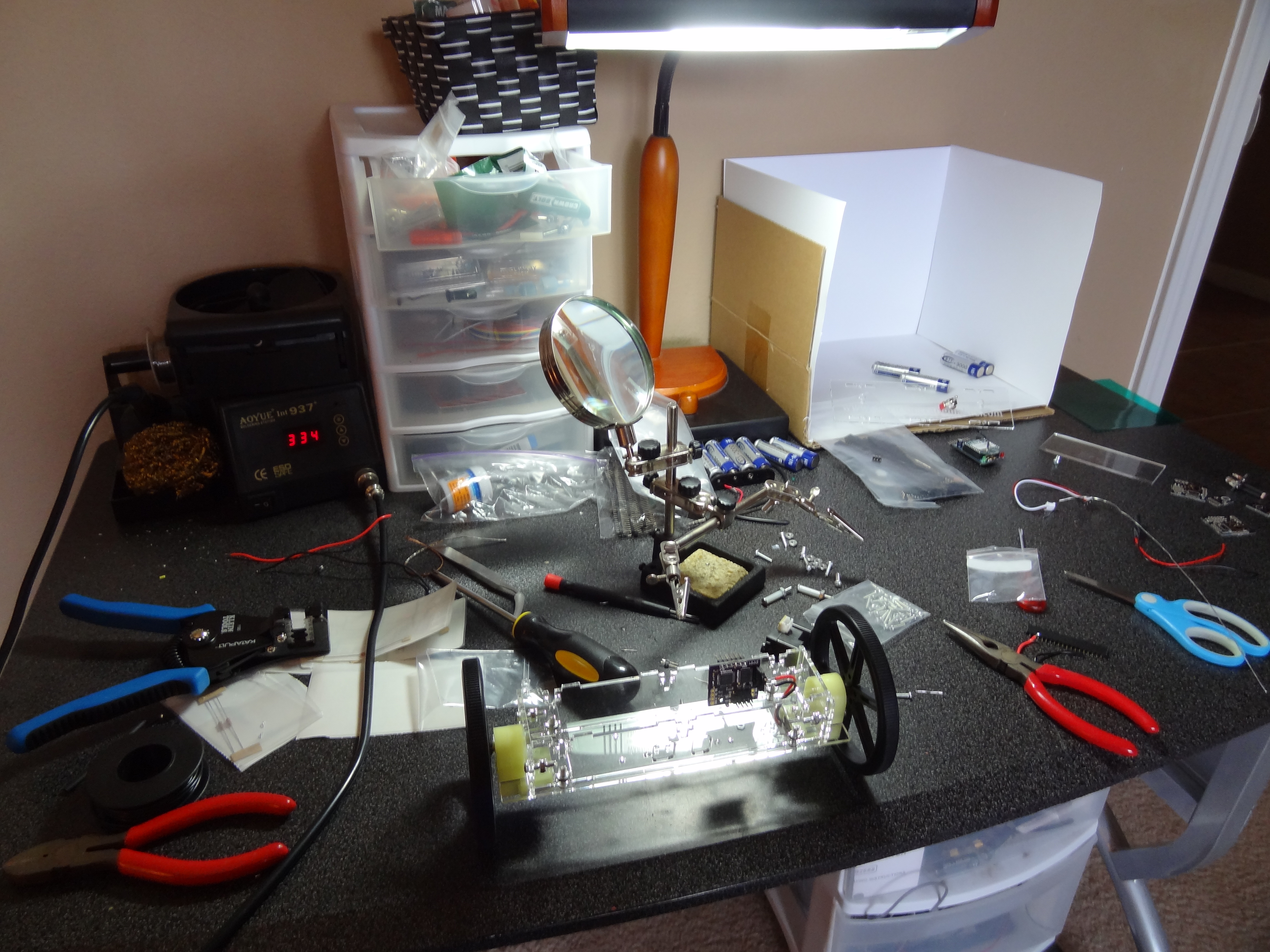
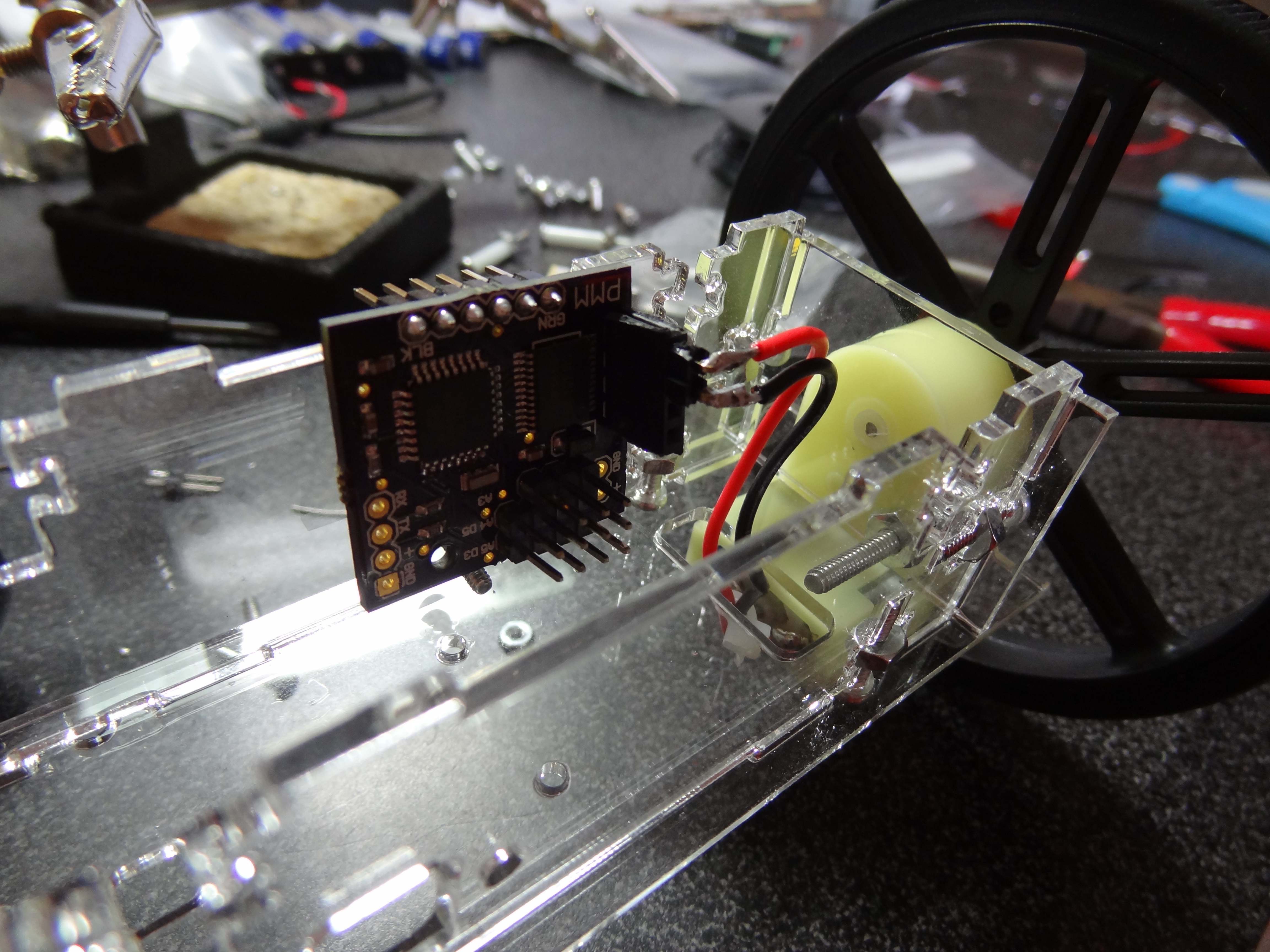
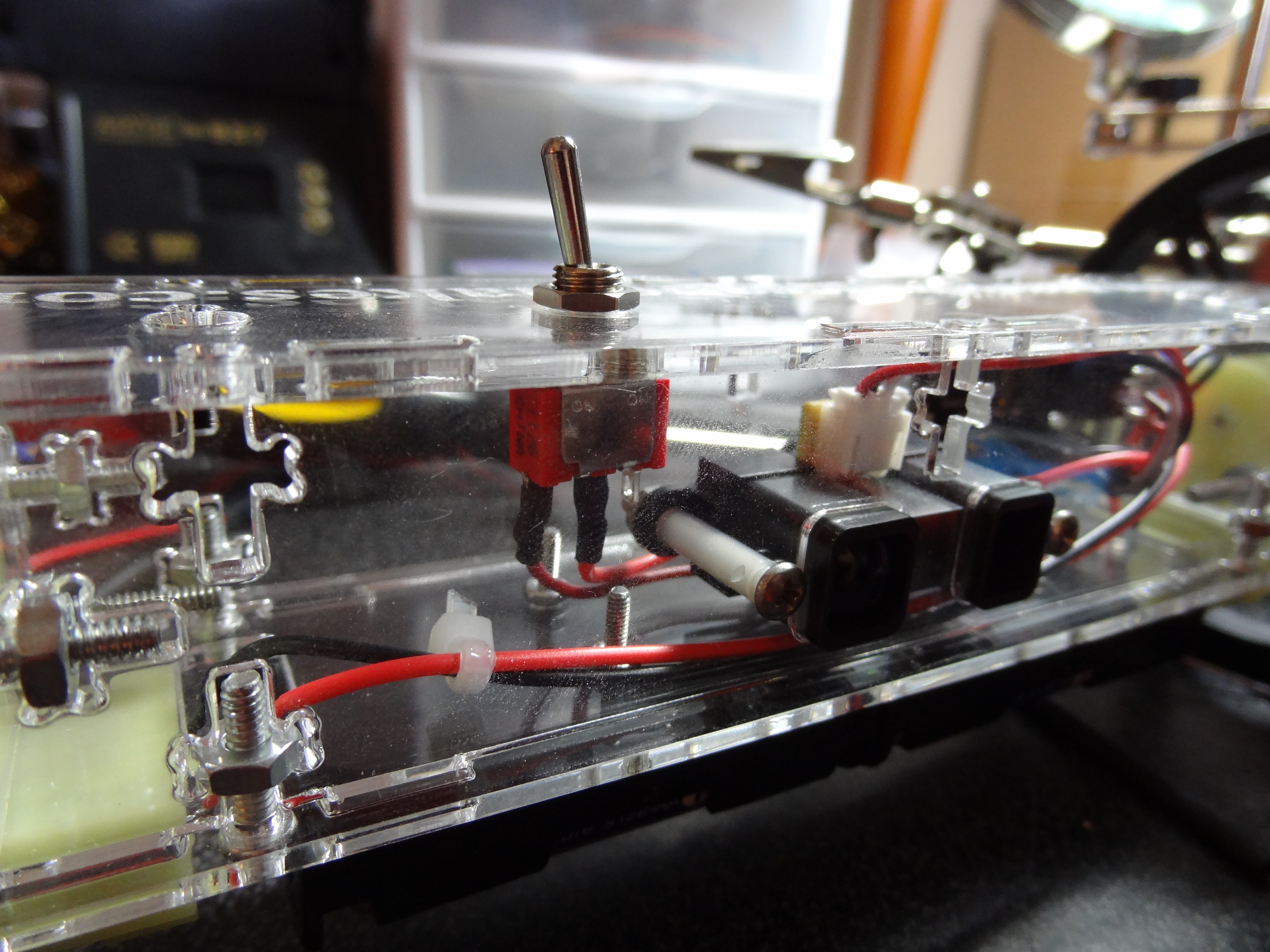
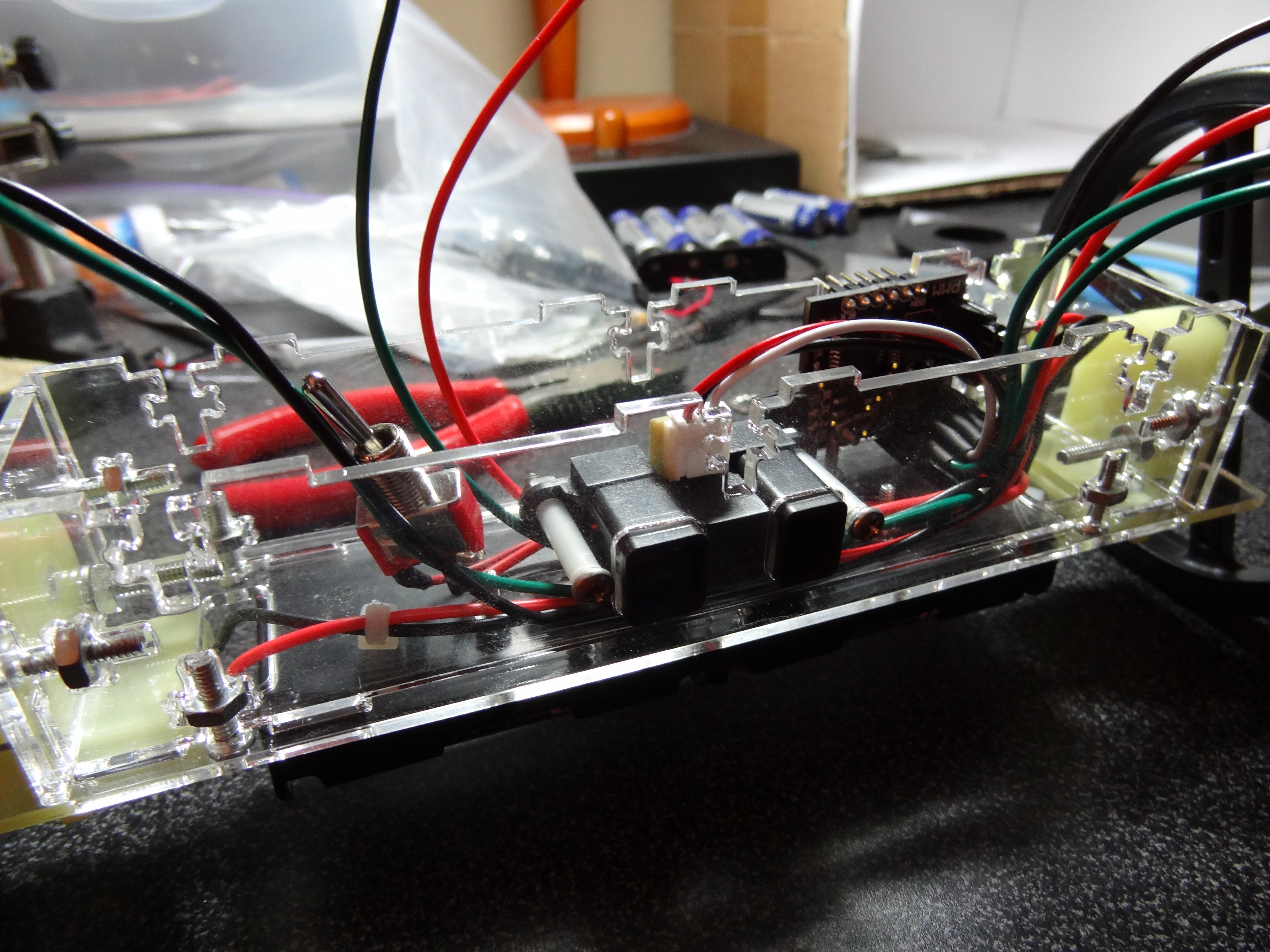
Putting It All Together
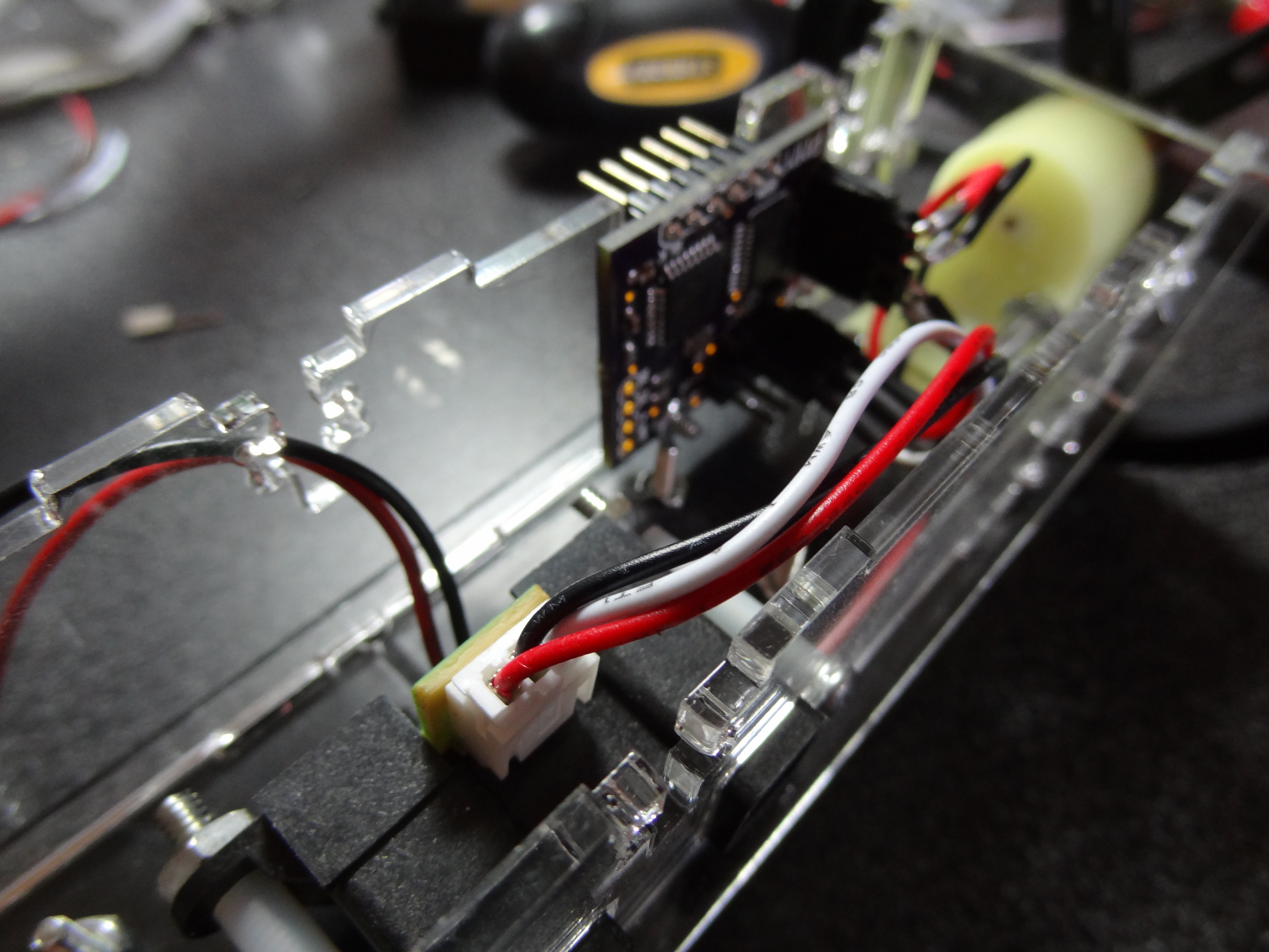
This is just the rest of the assembly which mainly requires wiring all the different bits together. The IR distance sensor, Xbee, motors, power, and light sensor / LED boards have to be connected to the main micro-controller board. This basically just required making female and male connections. I hope the pictures are self explanatory because there is not much to explain here.

Finished Robot