Chess Robot V1
Intro
This project was my first attempt at a chess playing robot. This robot never successfully played chess, so it was replaced with my Chess Robot V2, which does work. Information on this page may be irrelevant, but is kept as a reference to the beginnings of my chess robot.
The Chess Board
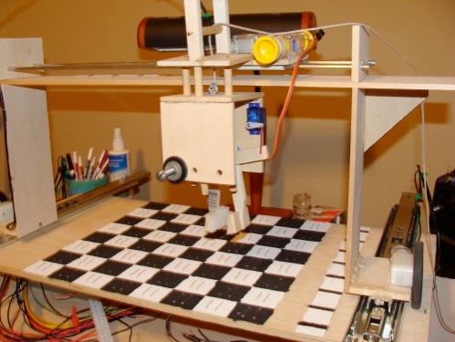
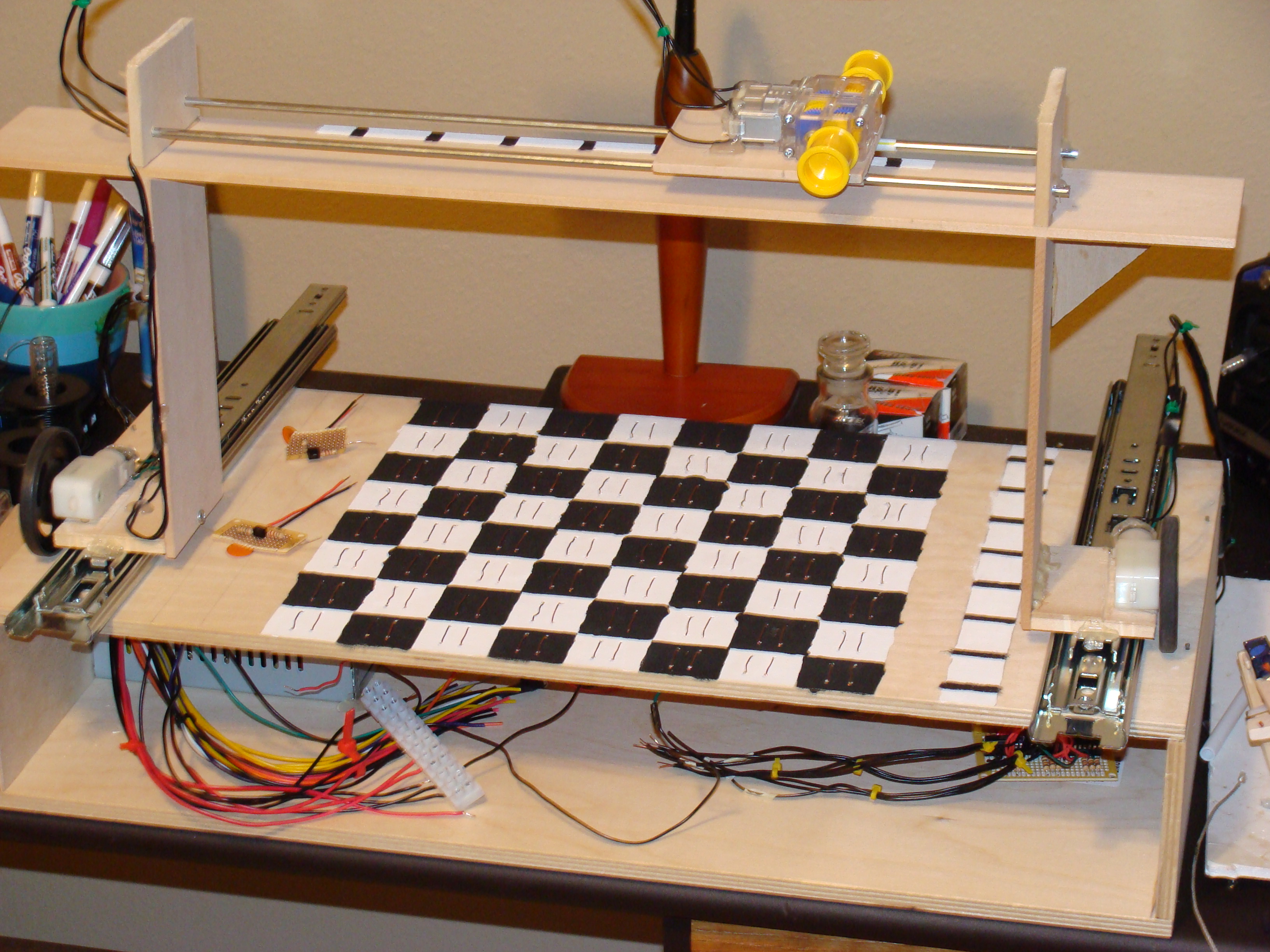
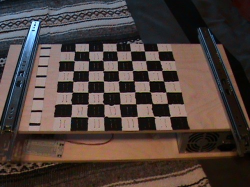
The chess board will be a custom made board that will have two metal contacts on the top of each square. There will be a metal contact on the chess pieces that will connect the two and make the input high. It will most likely have a box like base where all the electronics will go. There will be painted on stripe-like encoders on the side.
Moving The Pieces
This will be done using a gantry crane setup. It will use two gear motors to drive it back and forth over the chess board. It will be on a rail so it doesn't move from its course. It will have a servo gripper that too will drive on a rail back and forth over the chess board. It raises and lowers this gripper using a string and a reel. Im thinking one Tamiya dual gear motor box can be used to drive the arm and raise and lower it. There will be alternating white and black stripes on the side of the chess board so the gantry crane can move to the right places and keep track of where it is. This will be used on the top of the gantry crane as well to keep track of the arm. It will use a Pololu line sensor to read the line.
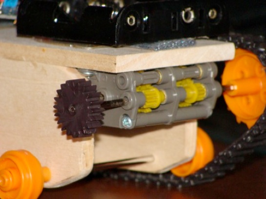
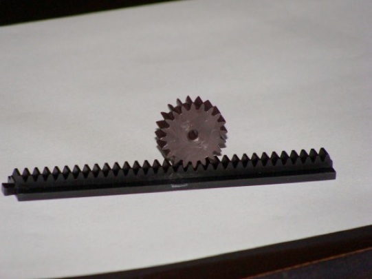
The gear for the rack and pinion fits tightly on the Tamiya dual gear box that is on one of my robots. So I will be buying one to use on this robot that will move the "sled" and arm.
Electronics
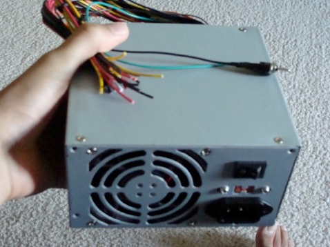
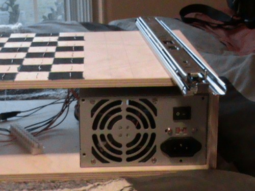
My modified power supply is finished. A 10w 10ohm resistor was added on the inside (bye bye warranty) as a load. And a switch was added. All the connectors were cut off.
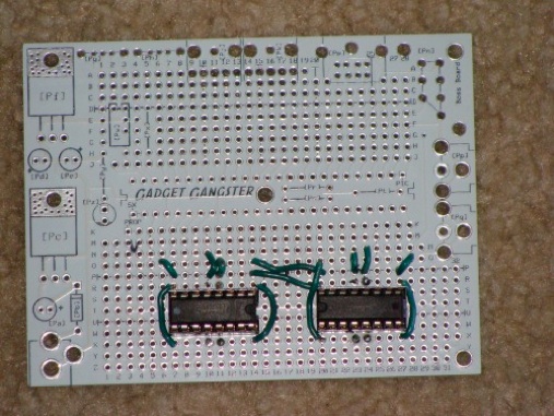
Here is my motor driver board. It is just two L293D ICs with the ground and power wired up. It will be able to drive four motors. I also have a chip for the servo which I will add later.
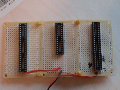
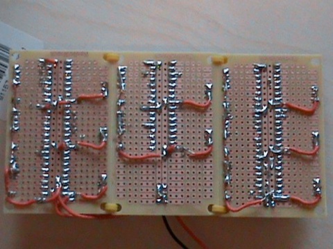
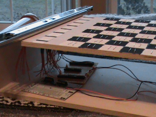
Here is my board for my 8 parallel to serial shift registers. The back is all the traces made for the chip and for the pullup resistors. They are 3 Radioshack boards zip tied together.
Hardware
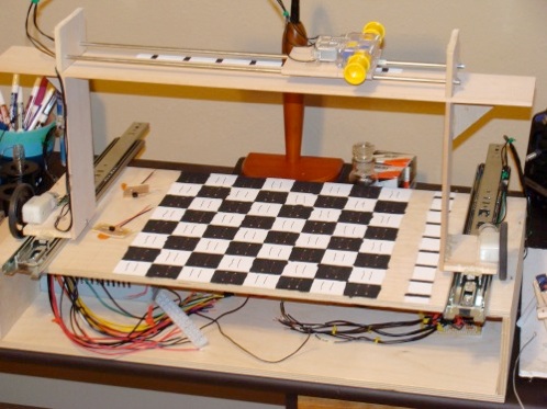
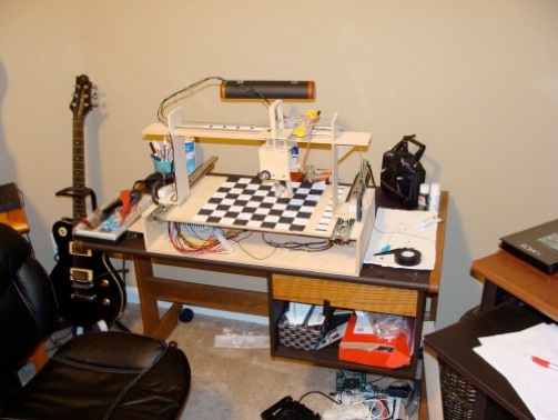
Below are pictures of the base of the chess robot where all the electronics are housed. It is not complete yet. The base is made out of thin plywood and just nailed and glued together. It is 12"x24"x4", so its not too big or small.
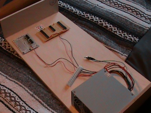
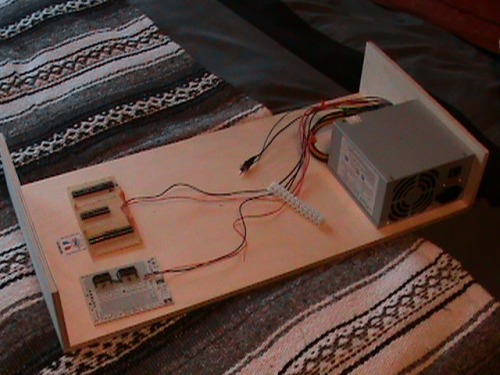
I got two drawer rails to use as the base of the gantry crane. They have very low resistance so I hope the gear motors can move the crane. That is about the exact lay out, so not much in looks will change besides the crane which is the next big part.
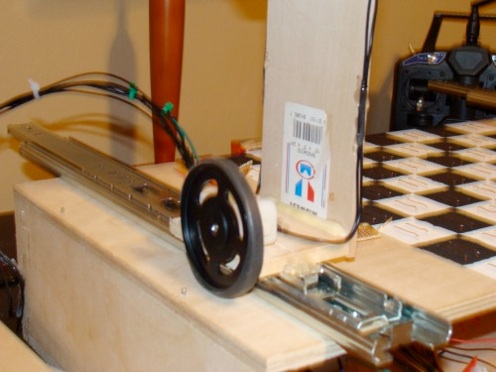
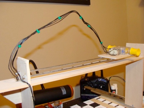
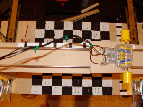
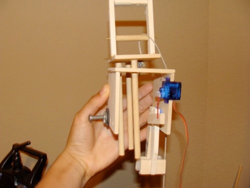
The crane was built at 8 1/2" high X 17" long. The railing system on top is made of two metal poles with a carriage that rides on two tubes back and forth on the rails. A string will be looped once around the motors spool to move the carriage back and forth. The gripper was made using two gears I had left over from making the gear box. The rack and pinion idea was dropped and now it is lowered and raised by a string on a spool. There are three poles acting as guides for the gripper as it lowers and raises. The gripper is just short enough to not run into the king as it moves around. It has some counter balancing weights to make it balanced. All the extra wire in the air is so the motors can easily move with some slack. The wires for the encoders and the servo must be added. I taped the gripper up in its position to show how it will look. That was just for demonstration purposes only. Some foam was added to the grippers fingers because it was not holding onto the pieces without it. Well thats about it. The best part is all the pictures, so here they are.