Autonomous Ground Vehicle
Intro
This project is an autonomous vehicle that is guided via an on board GPS and compass module. The GPS provides the location data to the micro-controller which processes that data and calculates the distance and bearing to the next waypoint in the mission. The compass provides the heading data of the vehicle to the micro-controller which is used to determine the amount of error in the vehicles current heading compared to the needed bearing calculated. Using PID calculations, the vehicle steers towards the next waypoint and when the distance calculations return a value within the threshold (a pre-determined radius at which the vehicle is considered to be at the waypoint) then the code switches to the next waypoint in the mission and repeats the process until it has reached all waypoints. Click here to download the code.
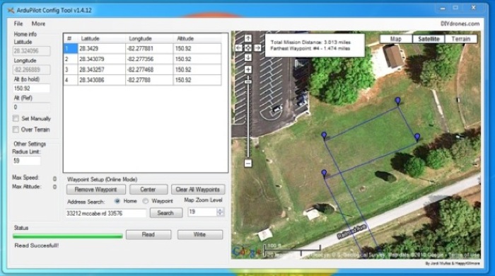
The planned waypoint mission driven by the vehicle in the video:
Constructing The Vehicle
Parts List:
- Compass
- GPS
- Truck
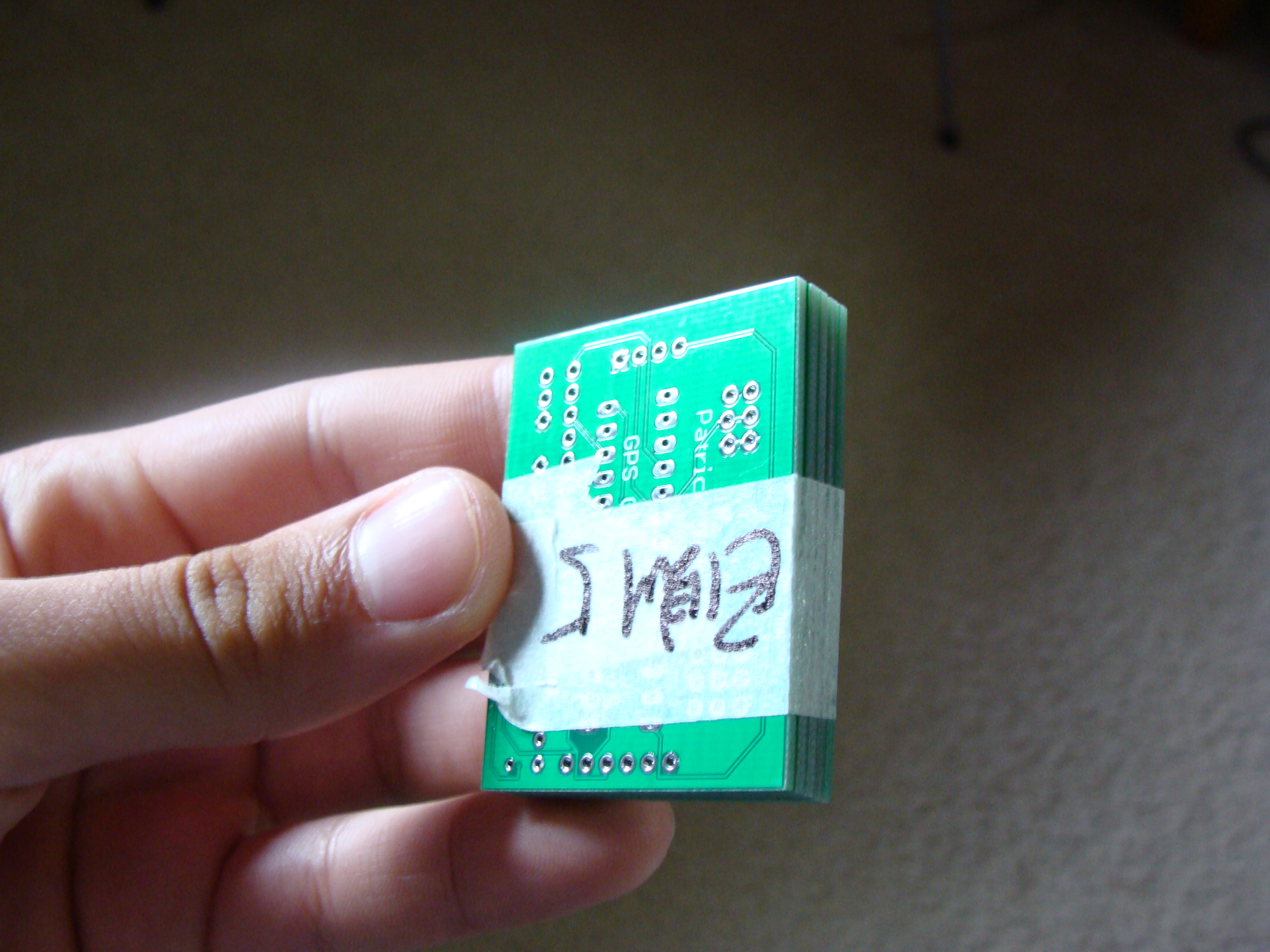
- PCB
- Atmega 328 (with Arduino bootloader)
- Shapelock plastic
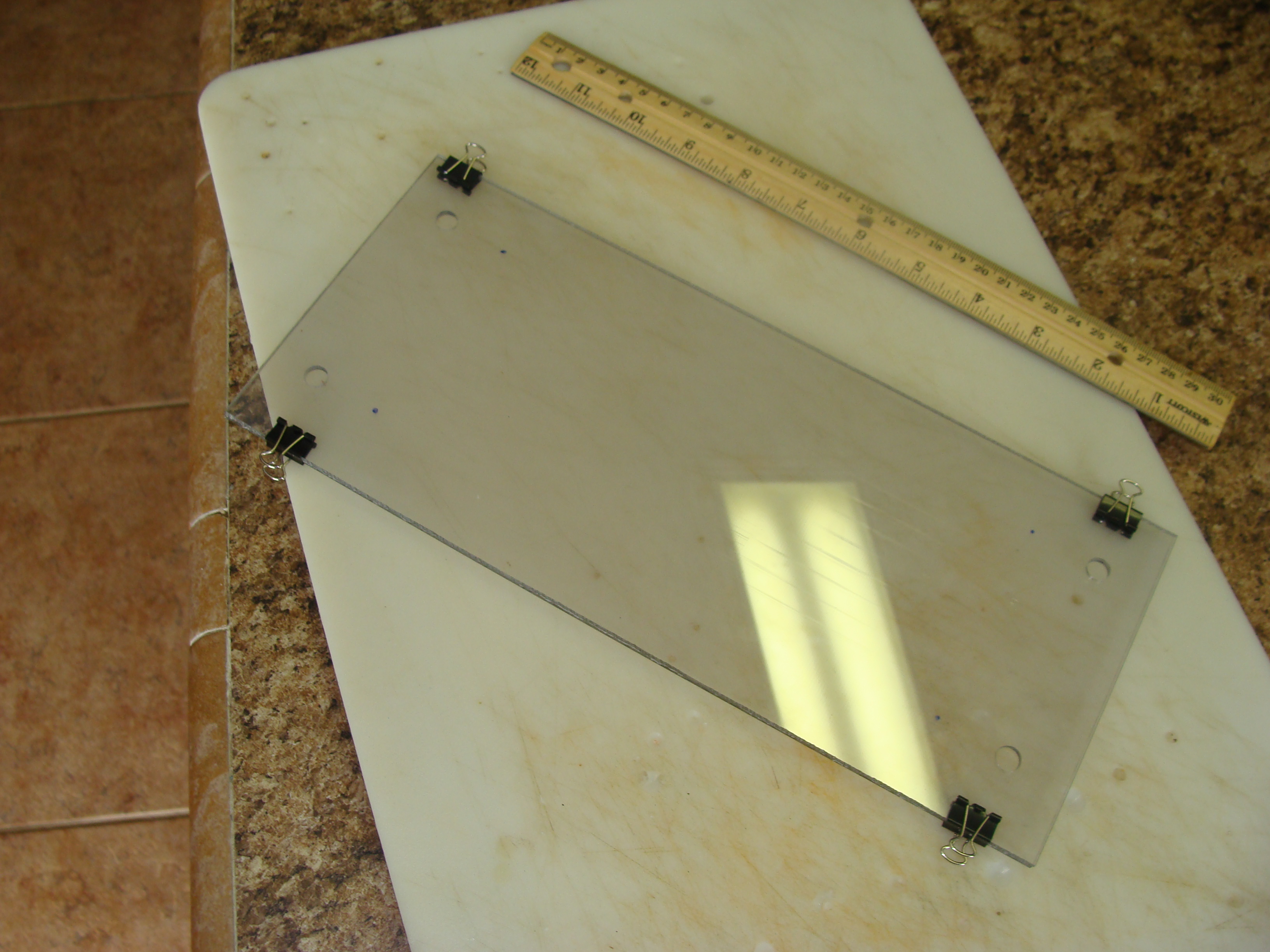
- 12"x24" lexan
- 4 Rechargeable AA batteries
- Plastic spacers
- Misc. nuts, bolts, and electronic components
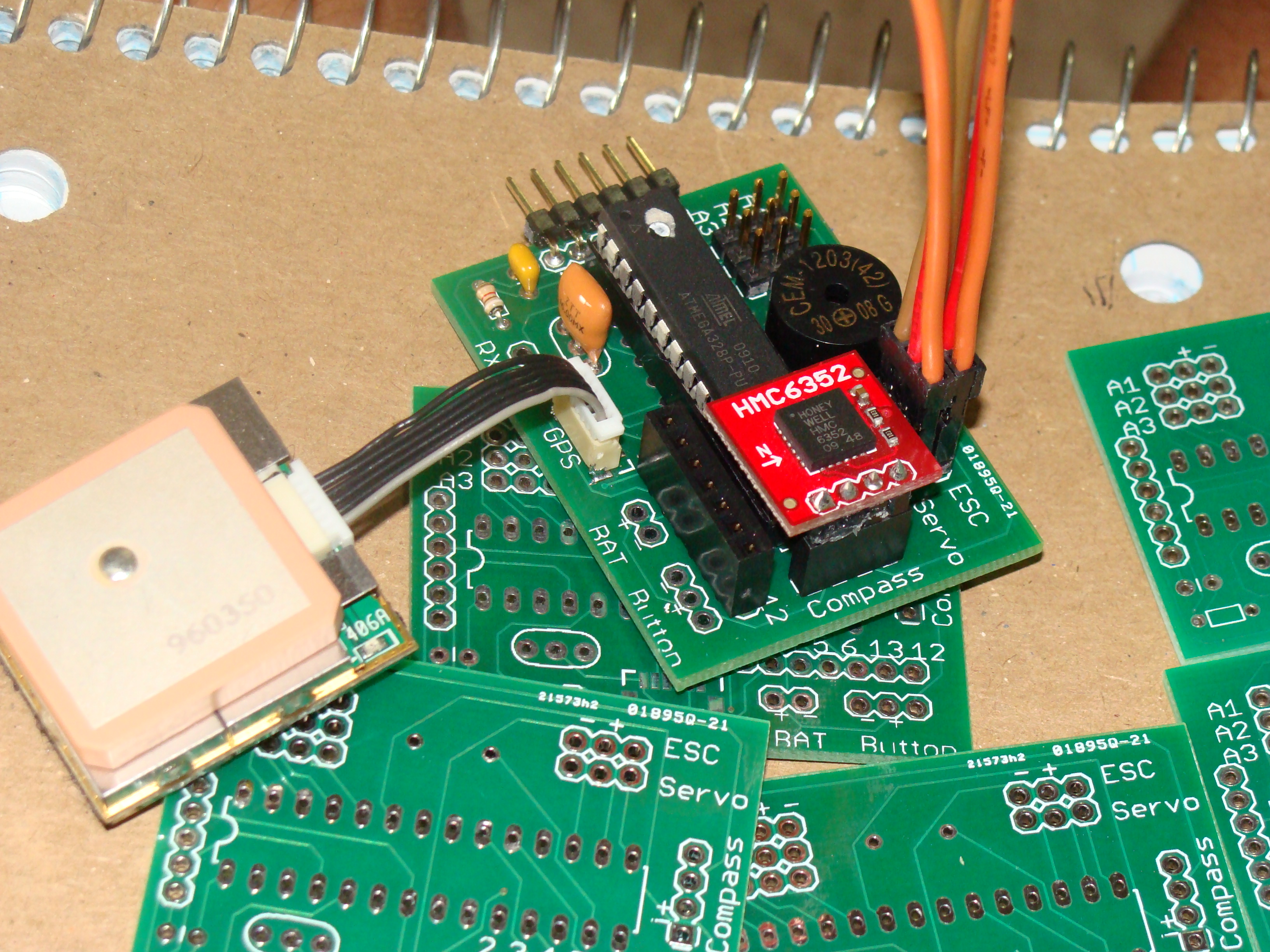
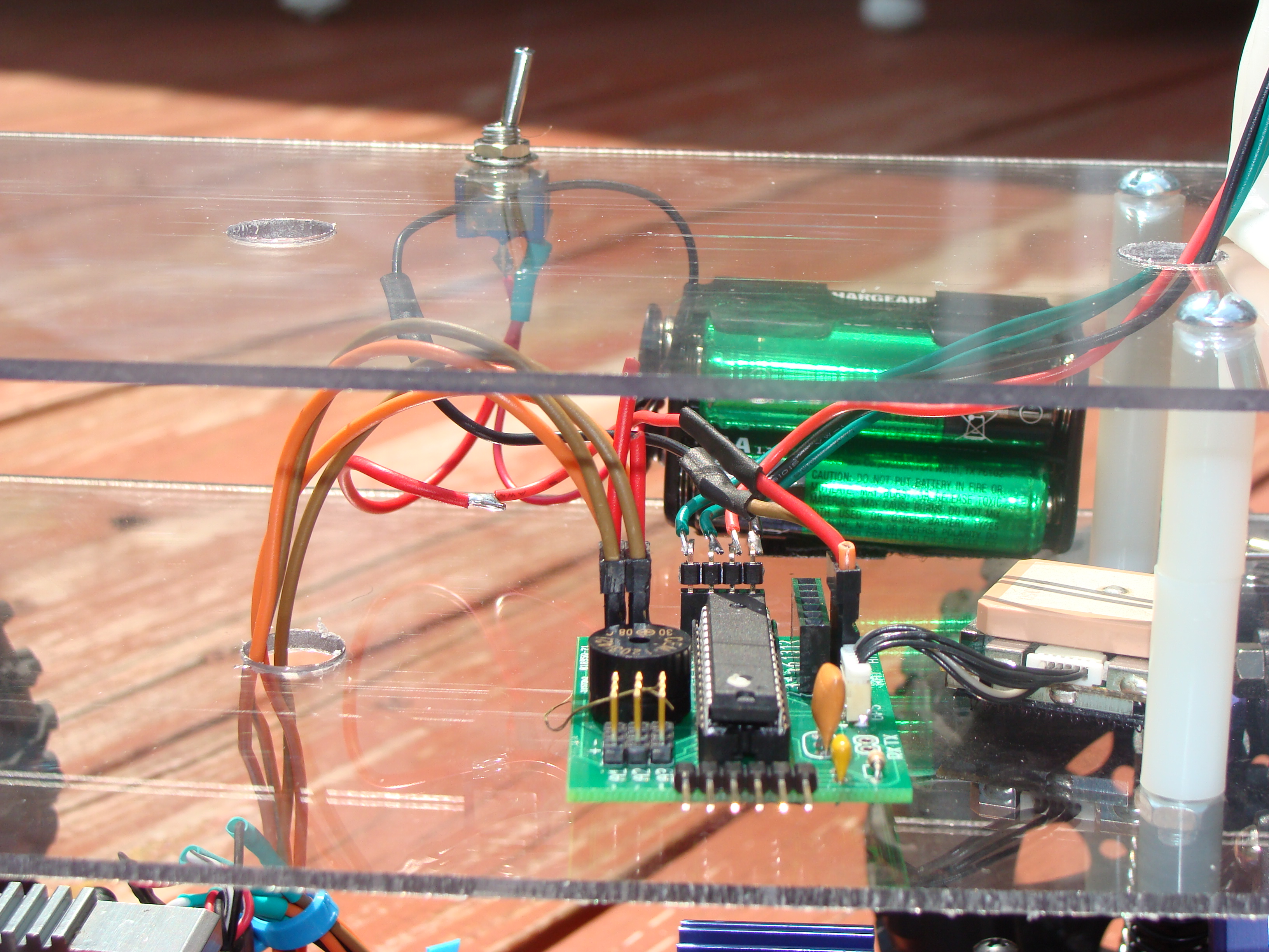
I designed a custom PCB for this vehicle to eliminate the rats nest of wires that would have been needed when using a general micro-controller. Any left over PCBs from this project are for sale in the store as always. The PCB’s design centers around simple plug-ability. The ESC, servo, GPS, and compass all have their designated “plugs” to be connected to, these “plugs” correspond with the code so the setup, code, and results could easily be repeated by others.
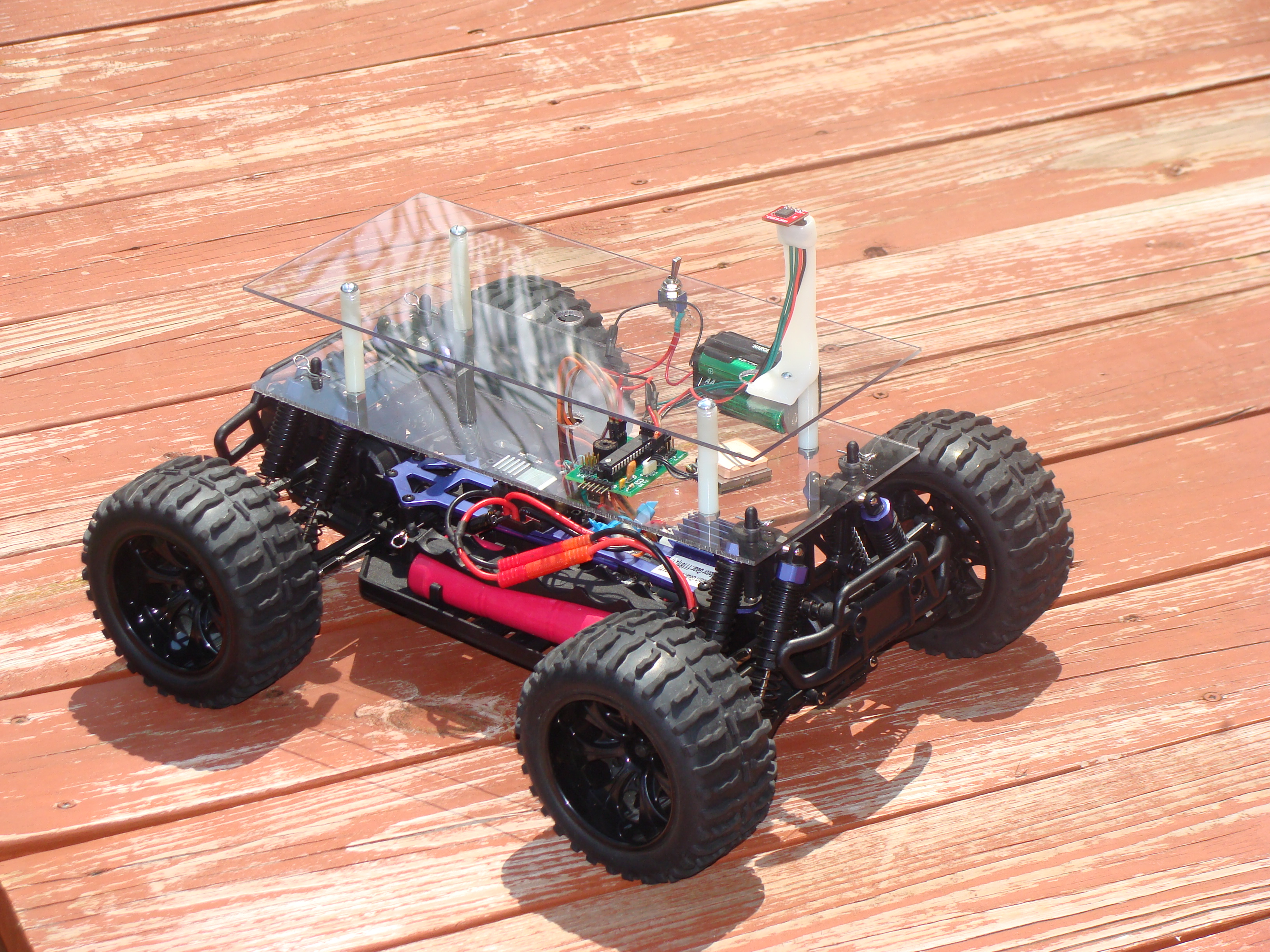
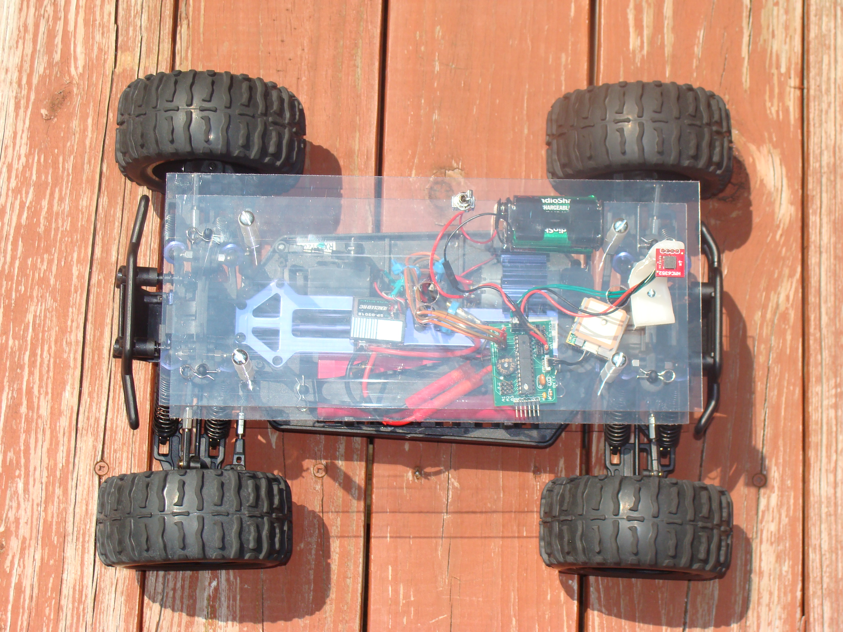
I built a dual platform and attached it to the vehicle. These platforms allow for more room and a flat mounting surface to add any sensors or actuators needed. This was a more practical solution than trying to mount everything onto the plastic shell the RC truck came with.


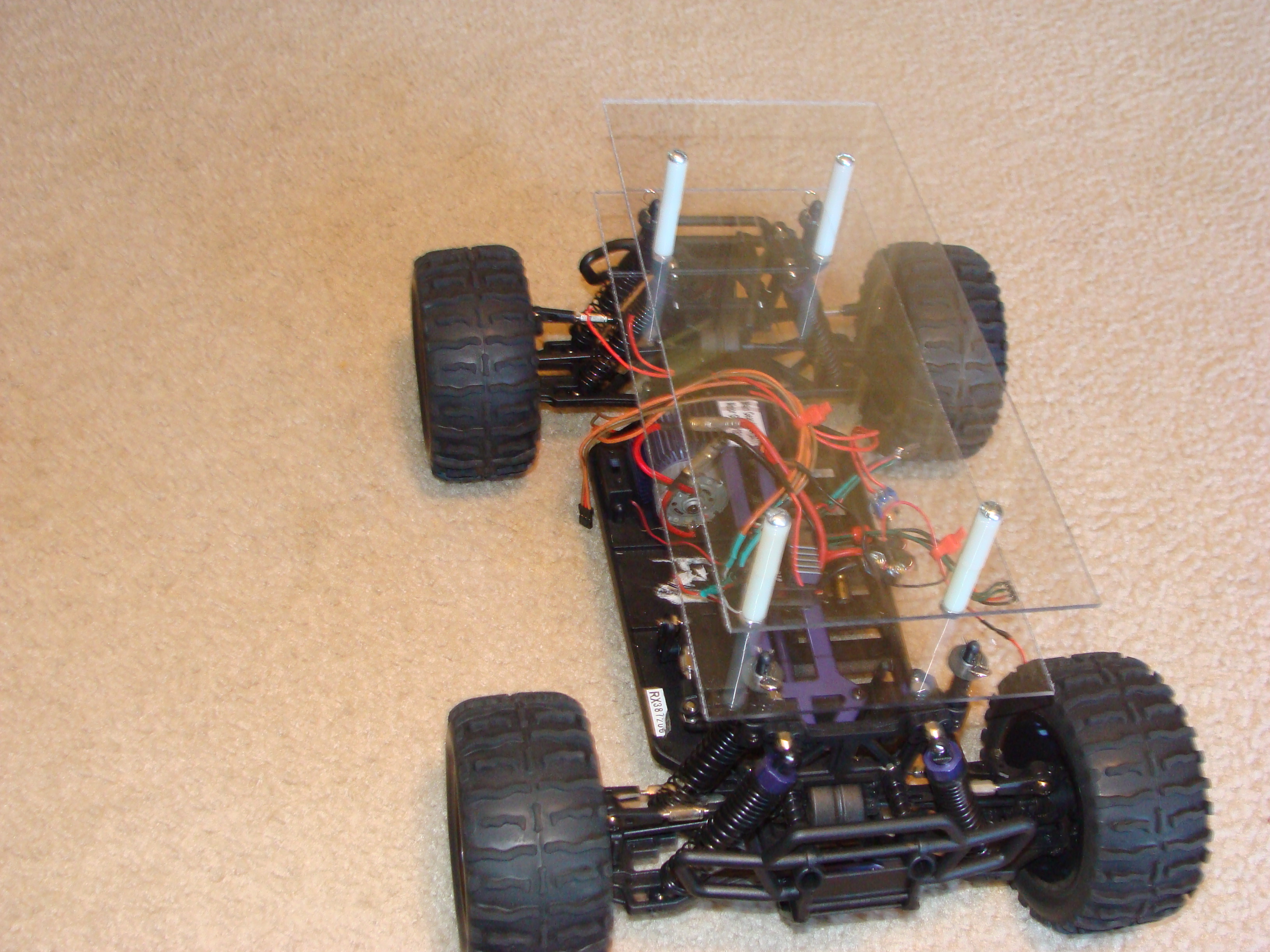
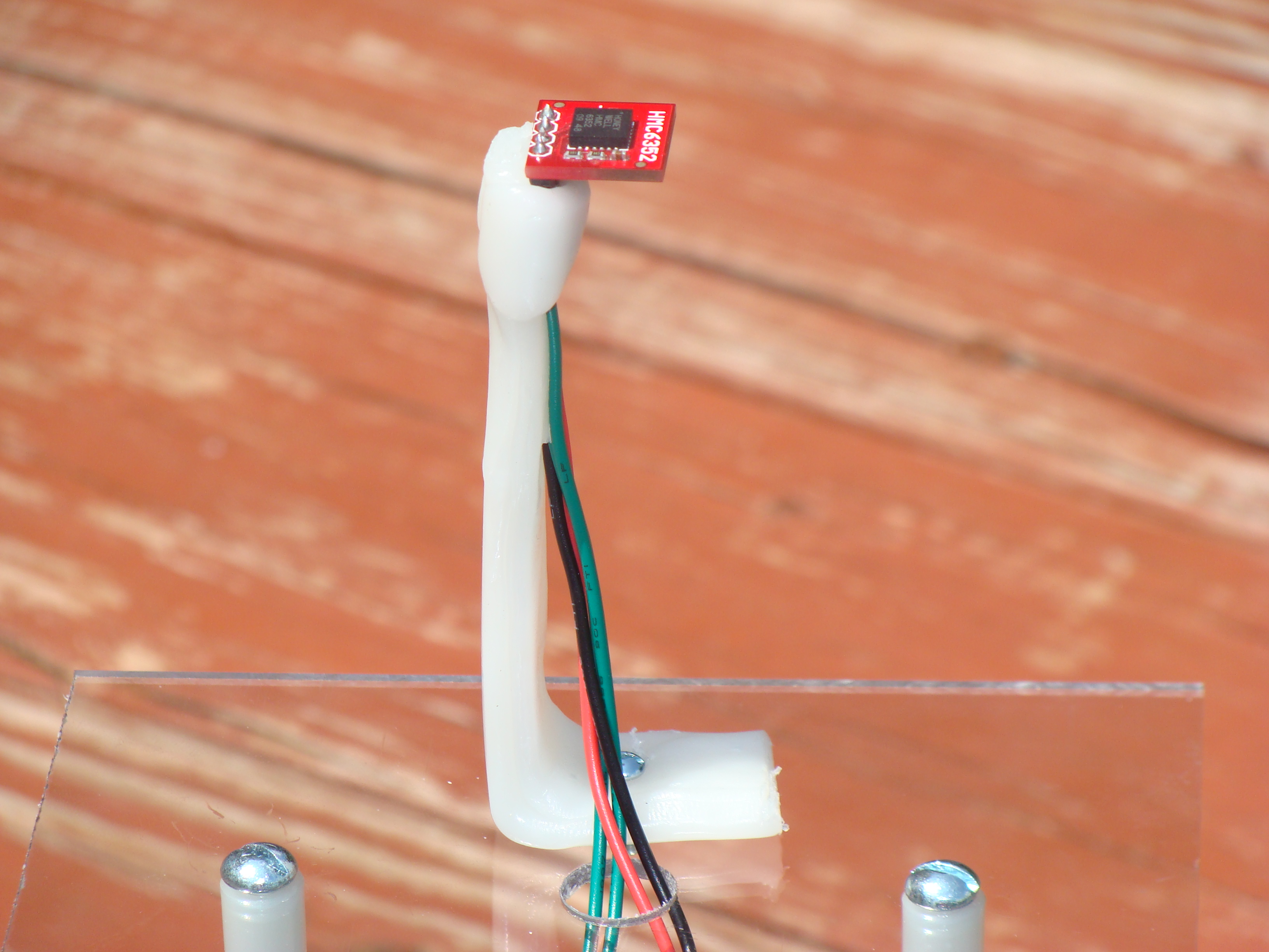
Below is the vehicle with the basic setup (GPS, compass, and my custom micro-controller board). The board, GPS, and the system’s battery pack are attached with velcro. The compass is mounted on the top deck on a custom ShapeLock plastic mount I made.
Constructing The Controller
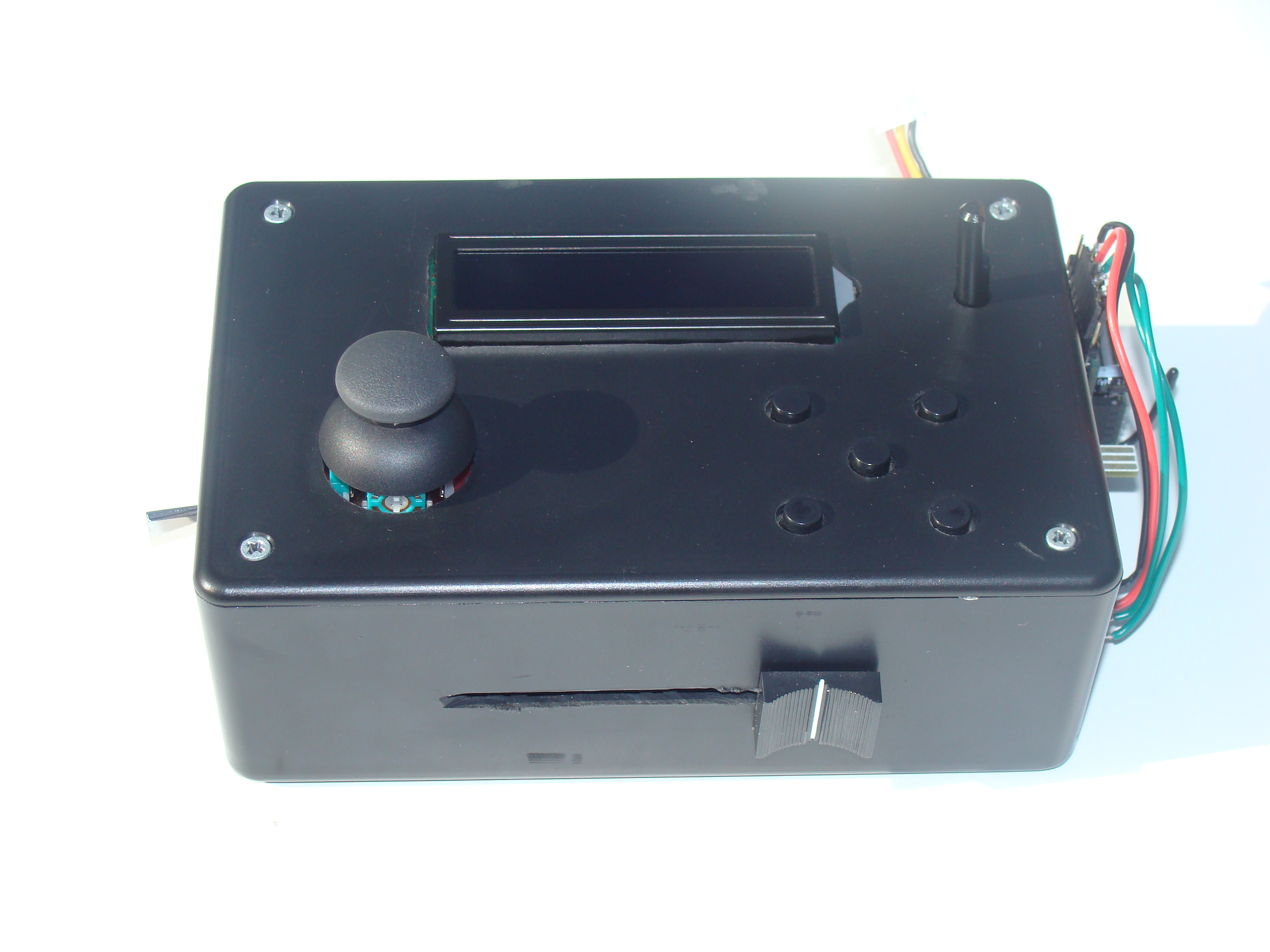
My custom RC controller will be put to good use in this project. The controller will serve as the user interface for the AGV. It will be used to switch modes, update waypoints, edit waypoints, control speed, change PD gains, and much more. I built the RC controller using:
- 16x2 LCD
- Plastic project box
- 5 Push buttons
- Dual axis joystick
- Joystick breakout board
- Xbee trasmitter and matching Xbee onboard the AGV
- 1000mAh 2S Lipoly battery
- Arduino RBBB
- Sliding pot
- Sliding pot knob
- Wii nunchuck adapter
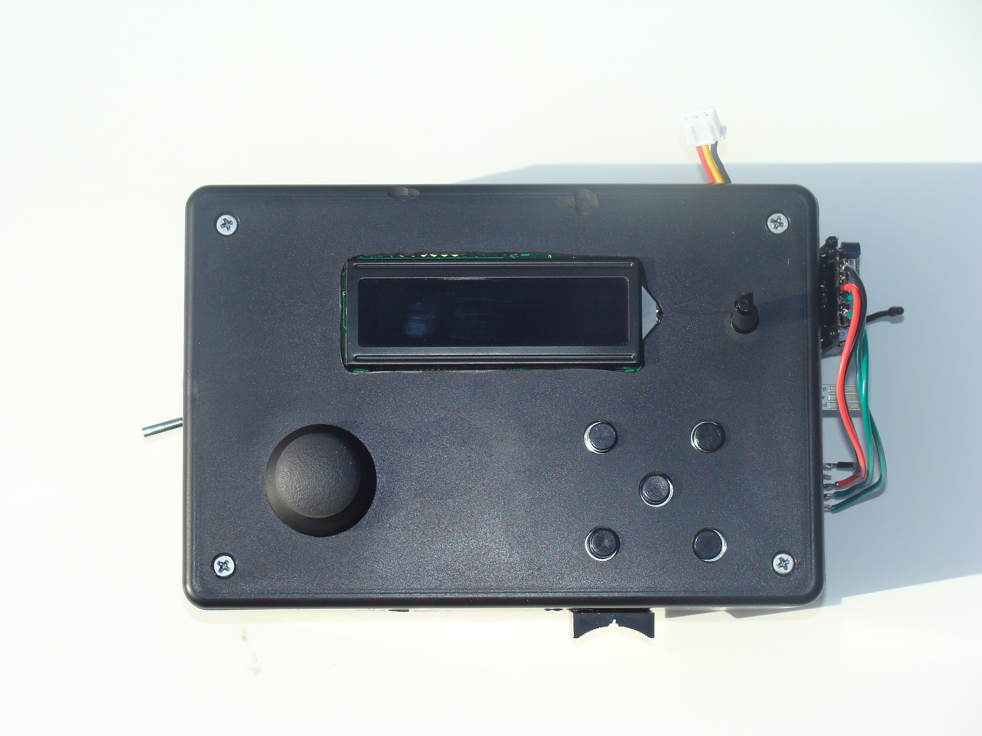
A drill was used to make holes for the joy stick and for the 5 button key pad that I soldered on a piece of perf-board. Everything was held in place with hot glue and then the necessary connections were made to the micro-controller. A little perf-board was used to distribute the power connections.
The Xbee is velcroed to the side of the controller with the antenna facing up towards the sky. The Wii Nunchuck adapter sticks outside the controller’s side next to the Xbee. The Wii Nunchuck will be used as a option to control the vehicle with using the Nunchuck’s built in accelerometers. There is a cable to connect the Xbee and the Arduino’s FTDI port together, this cable connects RX to TX and also supplies 5 volts to the Xbee. At the top of the controller is the charging plug for the onboard lipoly battery.

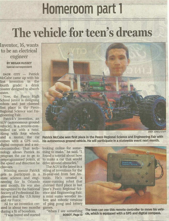
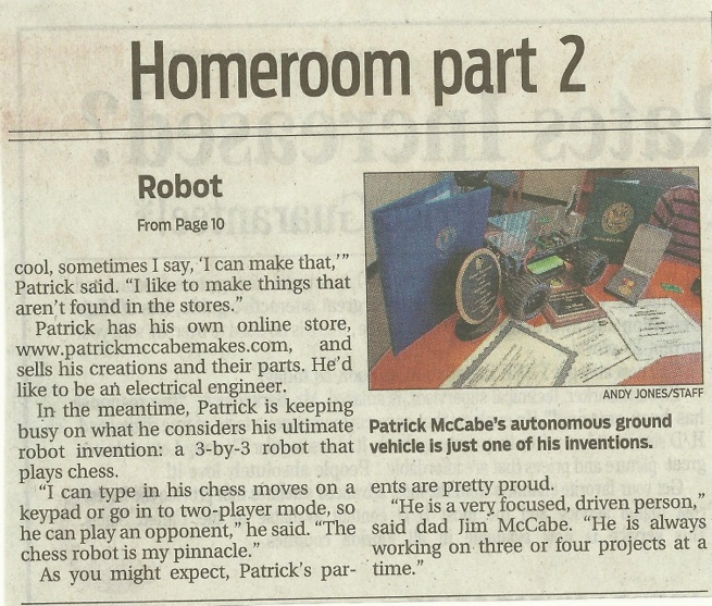
Newspaper
Some newspaper coverage I received.