MIT Light

Intro
The idea for this project popped into my mind one day when I was visiting MIT’s website. What I love about their website is that everyday there is a new “spotlight” post on the front page. However, not only is there a new post everyday, but there is also a new color scheme on the logo that matches the spotlight photo. I thought it would be very neat to make a lighted sign with an adapting MIT logo on it. The idea was to have the sign’s colors match the colors of the MIT logo on the website each day. In the end it would make for the perfect dorm room night light.
I instantly knew what I would have to do to accomplish this.
First I would need a program to do the folowing:
- Grab the MIT logo image from MIT’s website each day
- Extract the two different colors and break them into RGB values
- Transmit the two different colors to a sign that I would construct
- Have a simple user interface
The sign too needed certain characteristics:
- Display the MIT logo
- Use individually addressable RGB LEDs
- Be able to receive data from a computer program
- Be at least somewhat aesthetically pleasing
The Design
Like usual, I scribbled my initial designs down on graphing paper. I imagined the whole sign as a sandwich of layers, each one bolted onto the next. It would include a front plate, middle plate, and back plate.
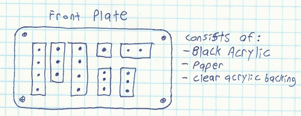
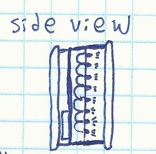
The Front Plate
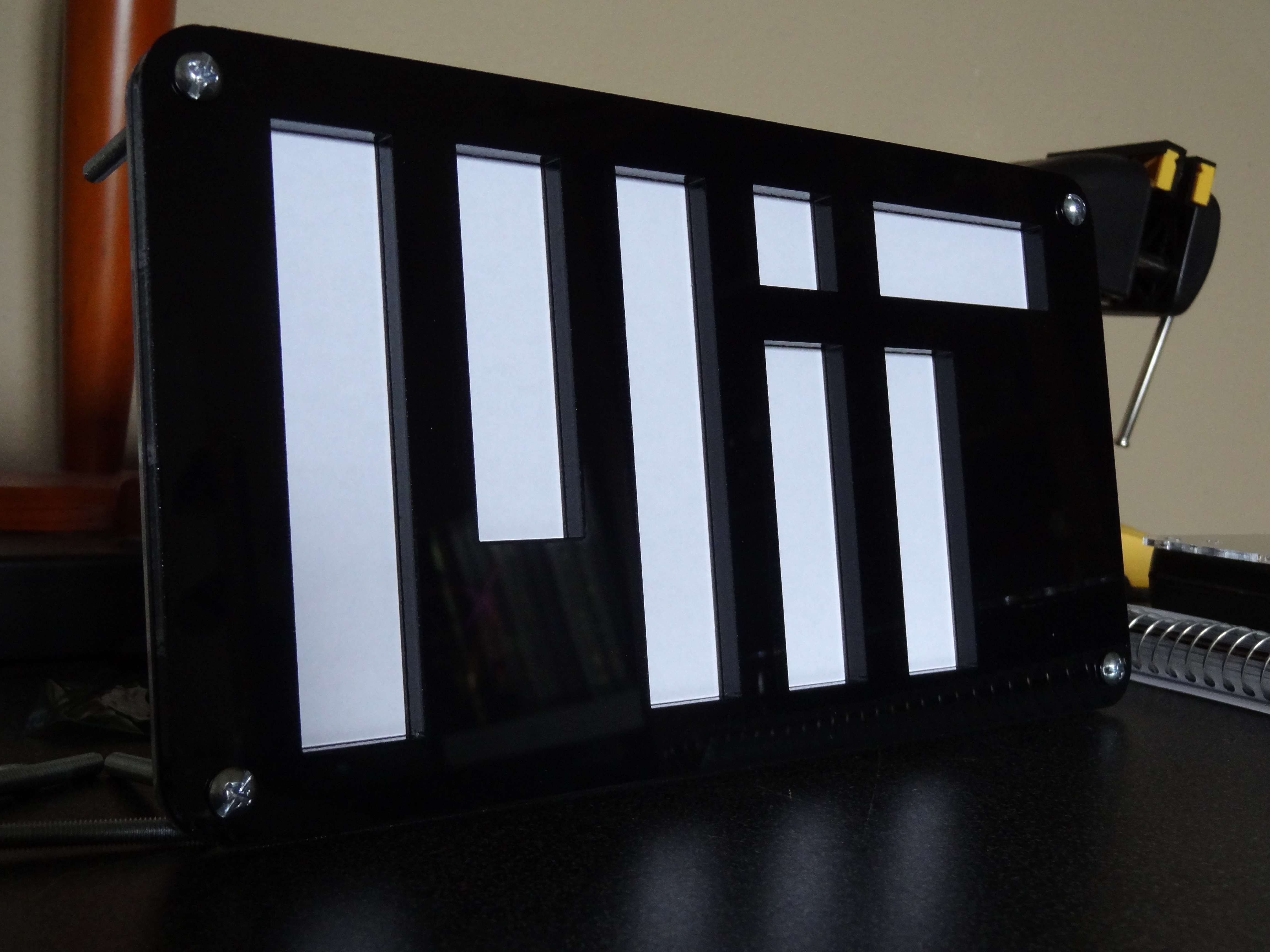
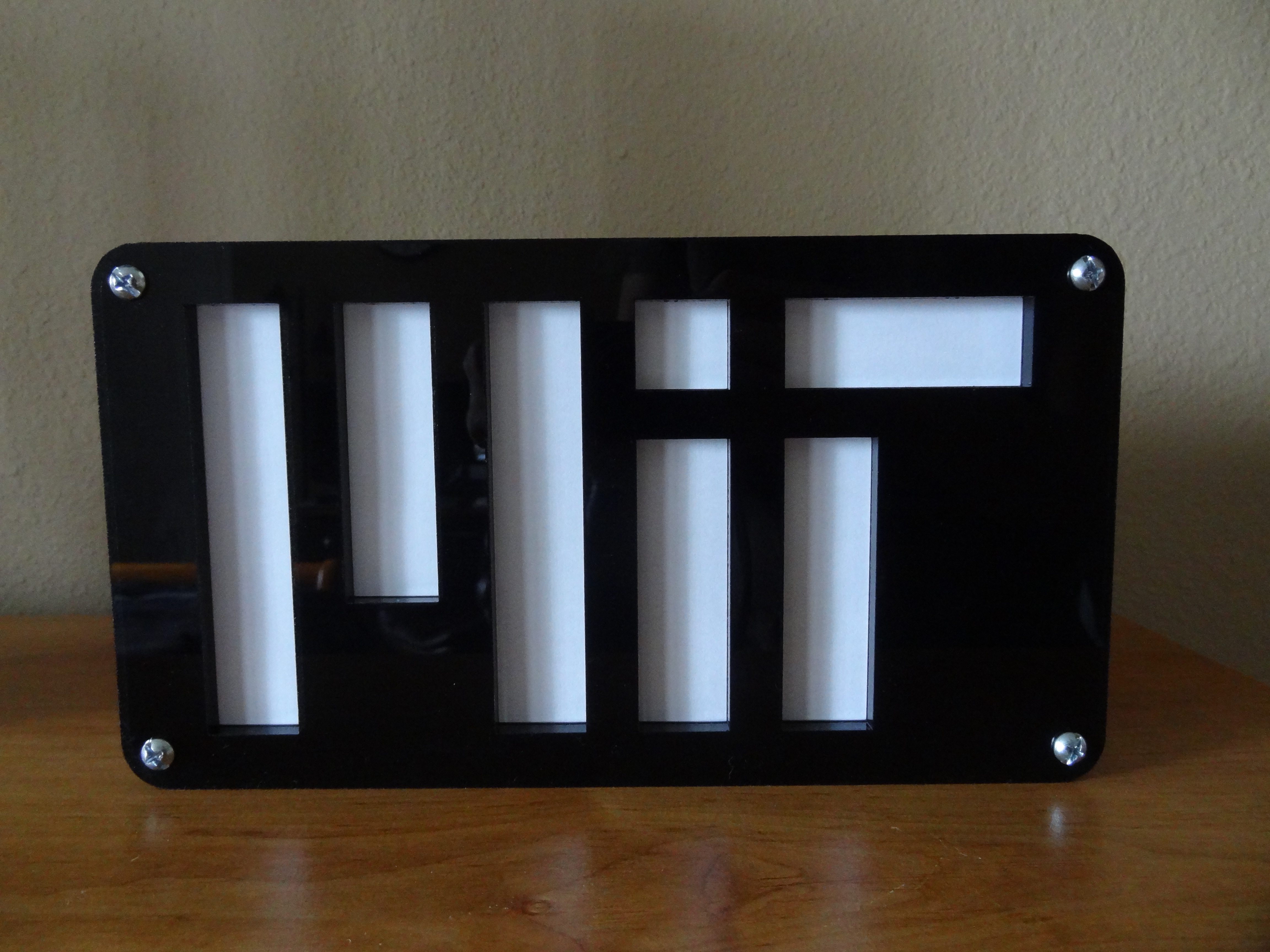
The front plate would consist of sublayers. The outer most layer would be made from black, opaque acrylic. Pieces would be cut out of the black acrylic so that the holes left would form the MIT logo. The opaque acrylic will let light pass only through the holes, which is necessary in my backlit design. The next sublayer in the front plate is paper. A simple white sheet of paper cut to the correct dimensions would serve as a diffuser. This would prevent the individual points of light from being seen. The last sublayer of the front panel would be a clear piece of acrylic, laser cut to have the same outline as the black acrylic. This piece of acrylic would hold the paper sheet in place.
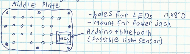
The Middle Plate
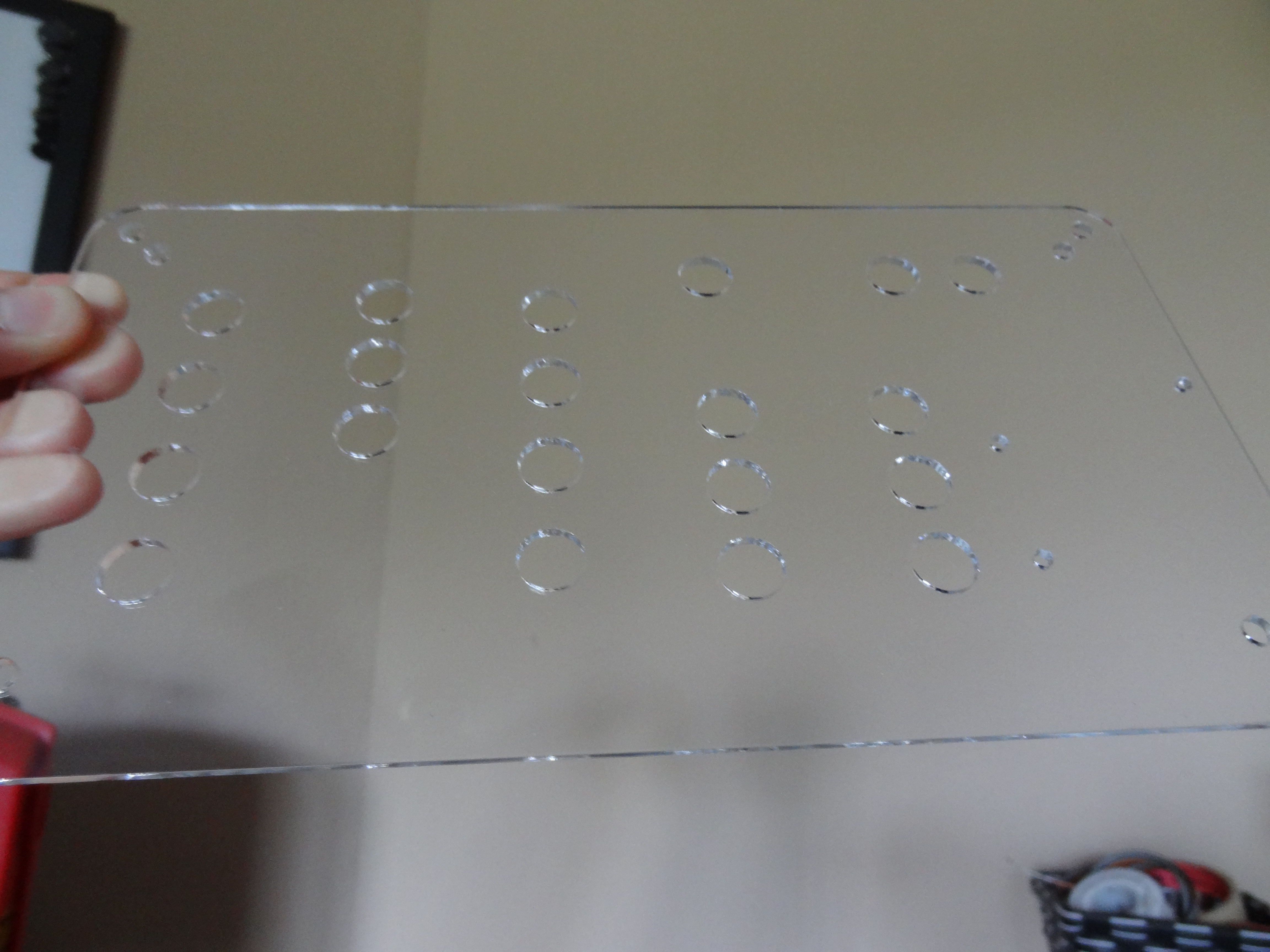
The middle plate would house the electronics and hold the LEDs. This plate would be made from clear acrylic. The LEDs would be arranged in a pattern that would light up sections of the sign. Mounting holes would allow the Arduino micro-controller to bolt onto the back of this plate.
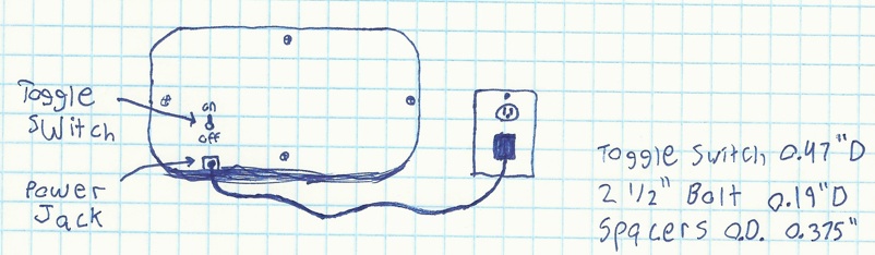
The Back Plate
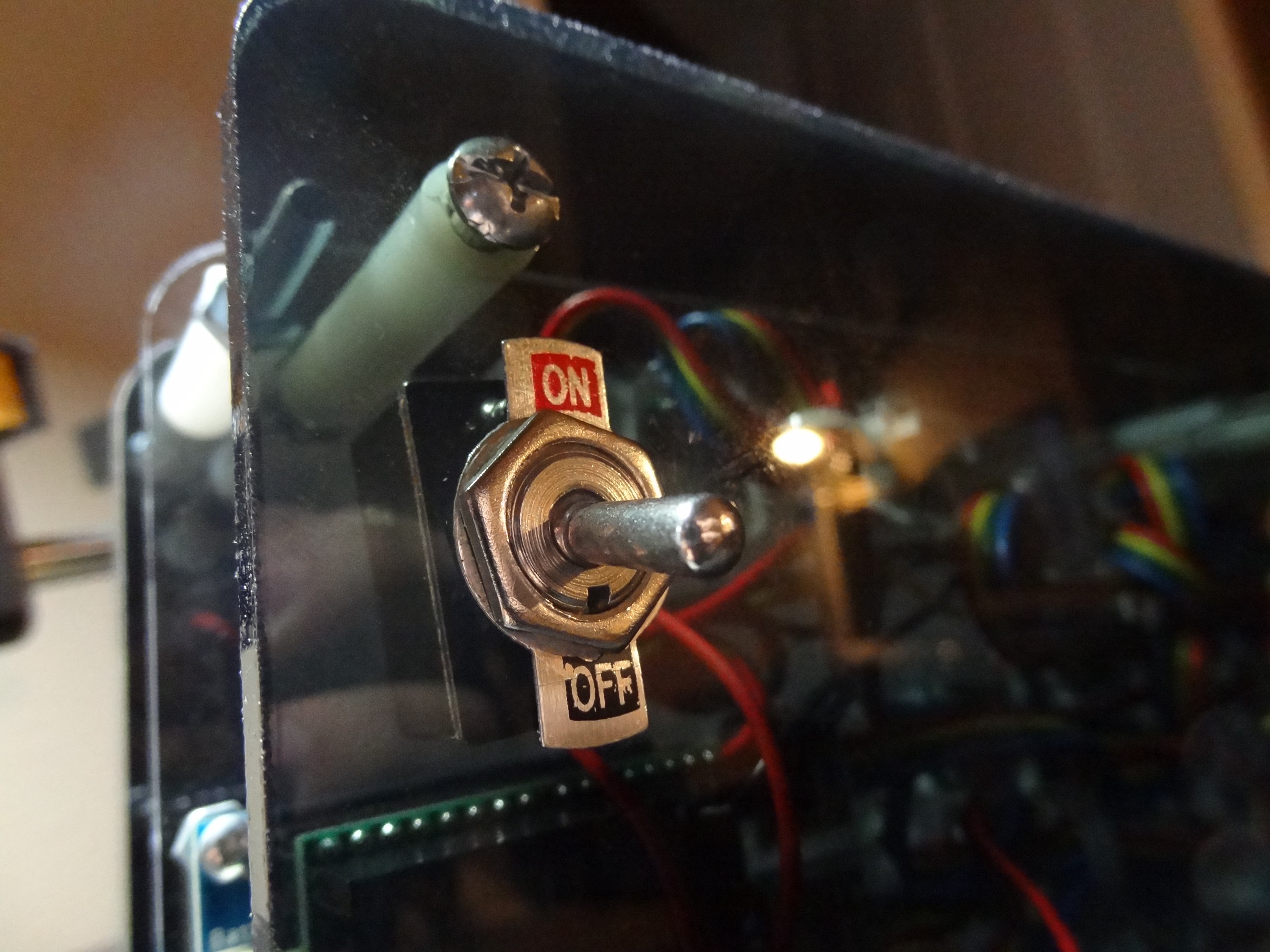
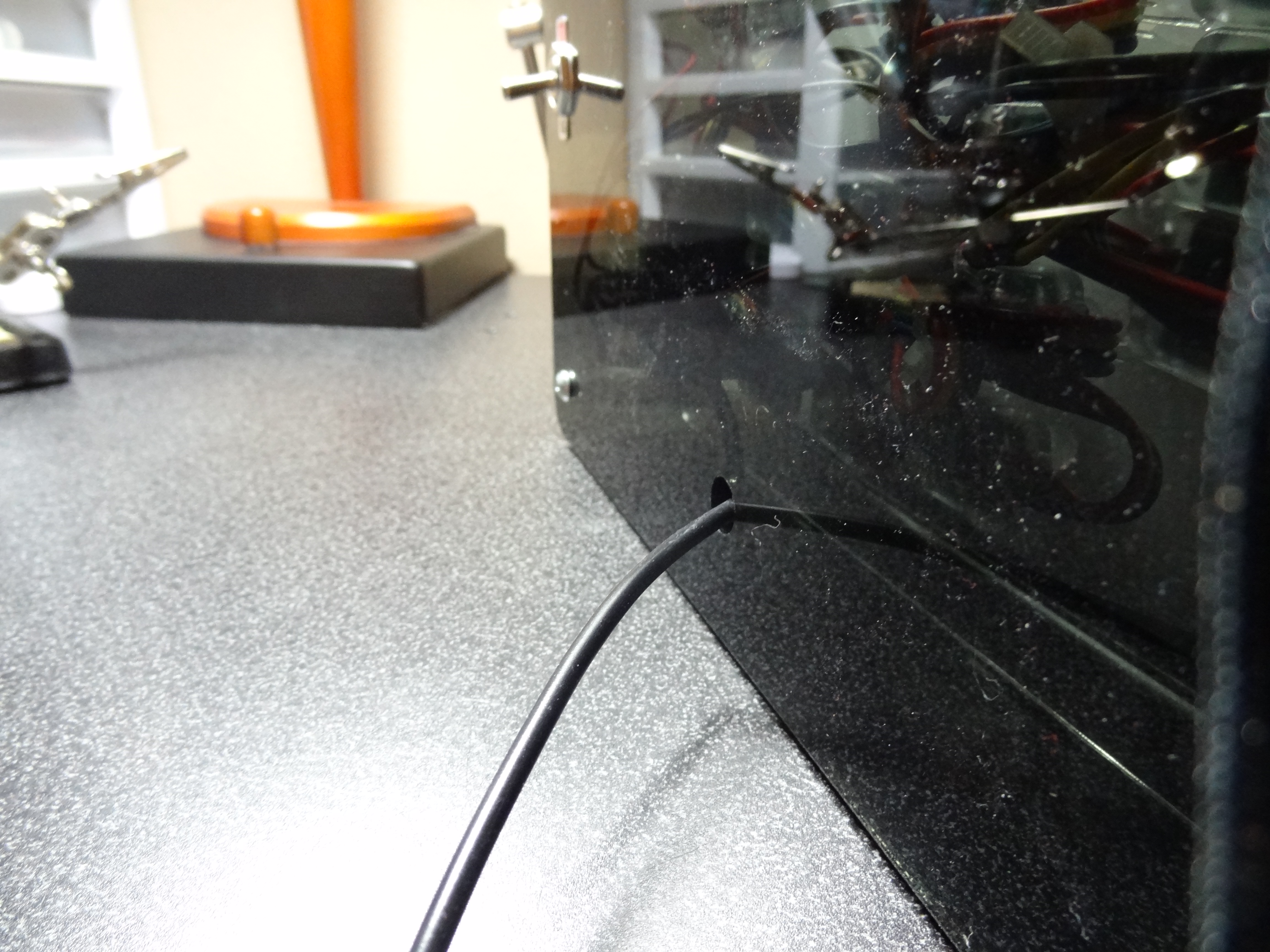
The back plate would have an on/off toggle switch and a power jack. This plate would be made out of the same black acrylic that was to be used for the front plate. In the end, I could not incorporate a power jack that faced the back. However, the last thing I wanted was a silly power cable coming out of the side of my beautiful sign. So I decided to have the power jack face the side and have the power cord come out of the back through a hole. More on that later.
Prototype
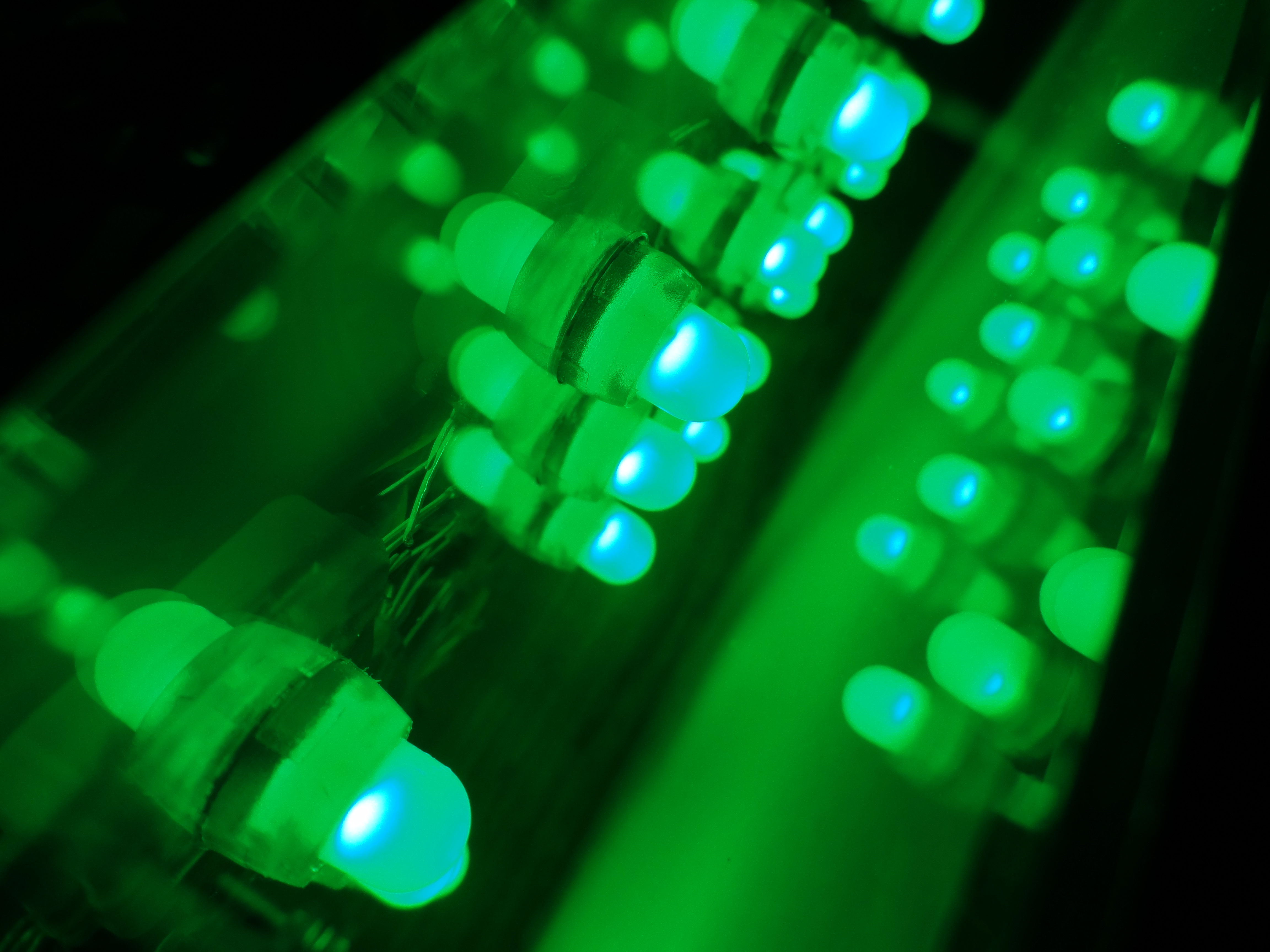
I constructed a simple prototype using my sketches. I wanted to see how well the LEDs would light up the sign. Paper was used to simulate the front layer. You can view the test video below. From this test I learned a little bit about the spacing of things.
CAD
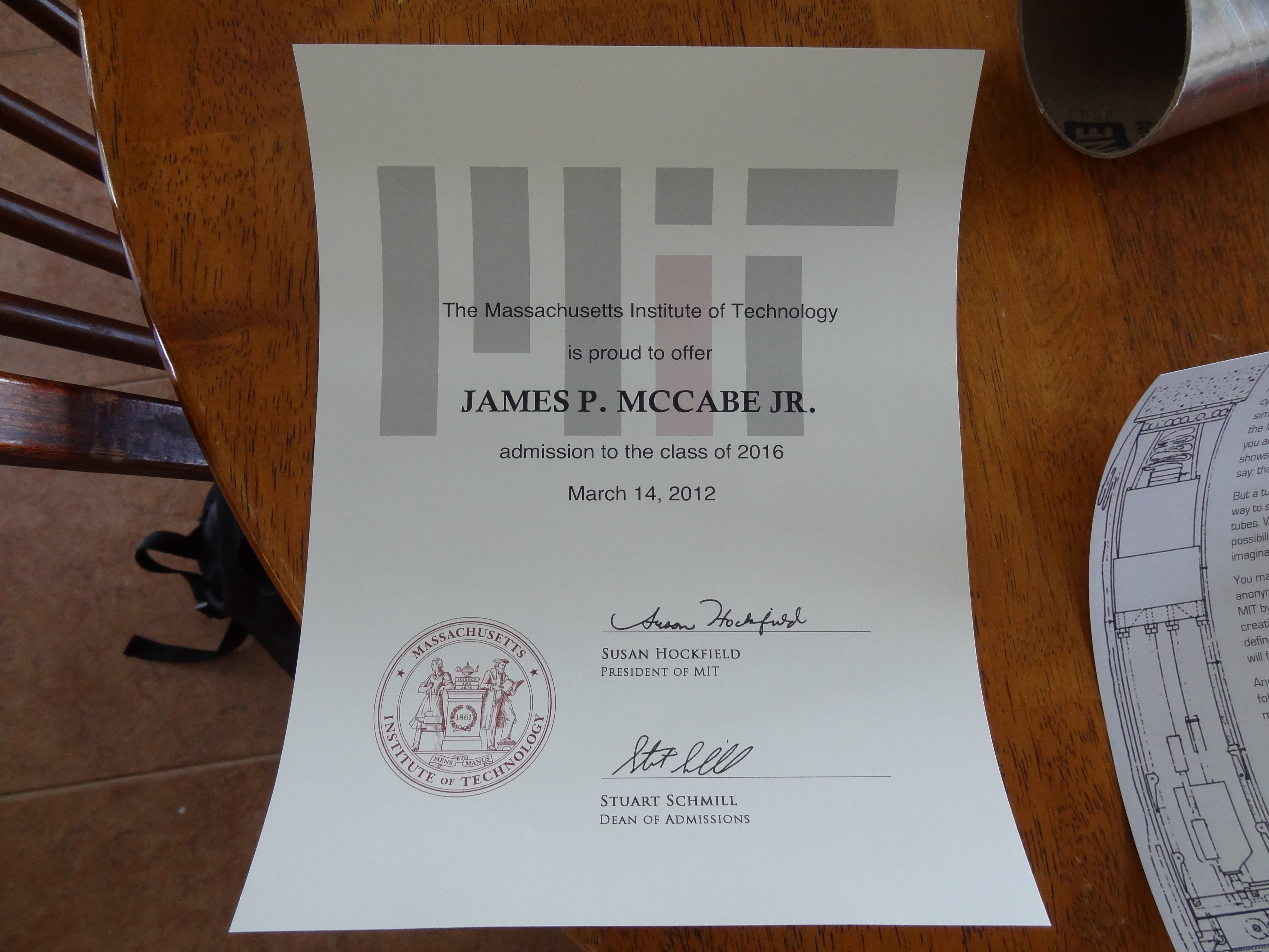
I used my admissions letter from MIT and my digital calipers to get the dimensions of the MIT logo.
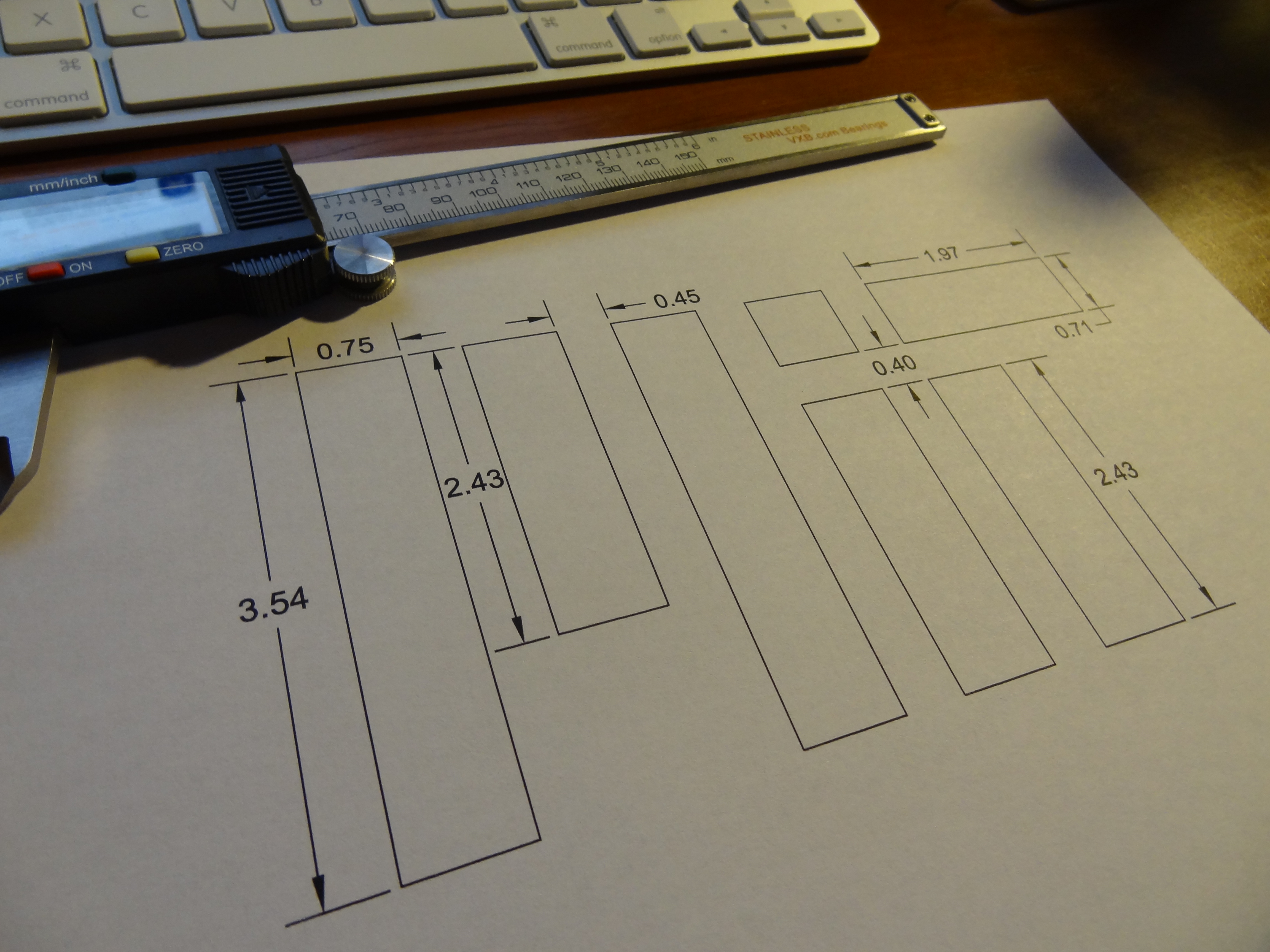
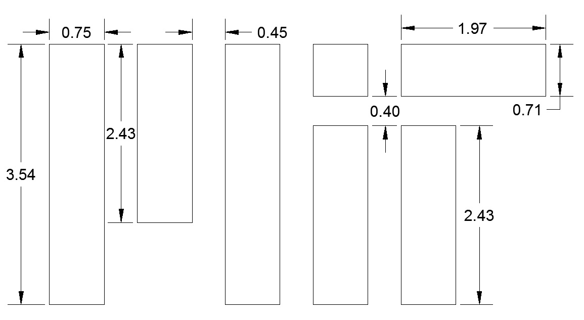
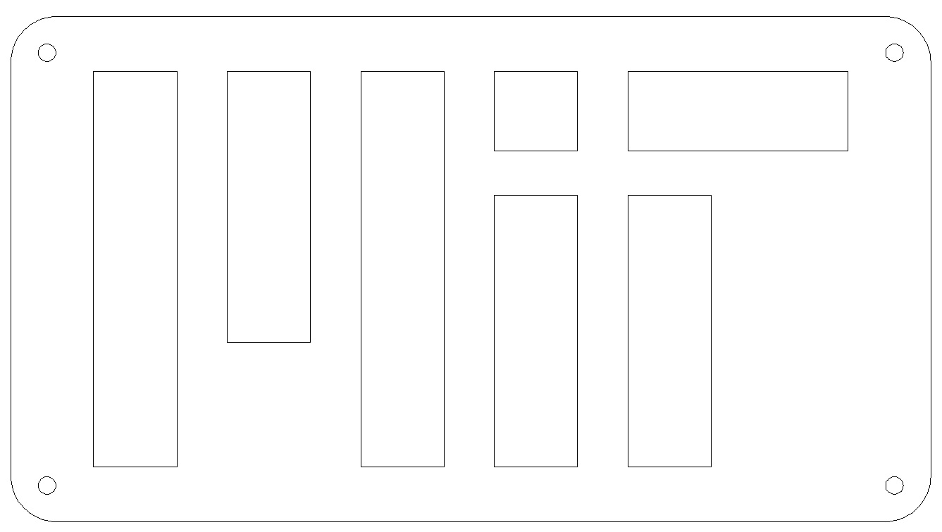
I drew my design in AutoCAD so I could later laser cut it out. You can click here to download the AutoCAD file. Below are screen grabs of the final CAD design.
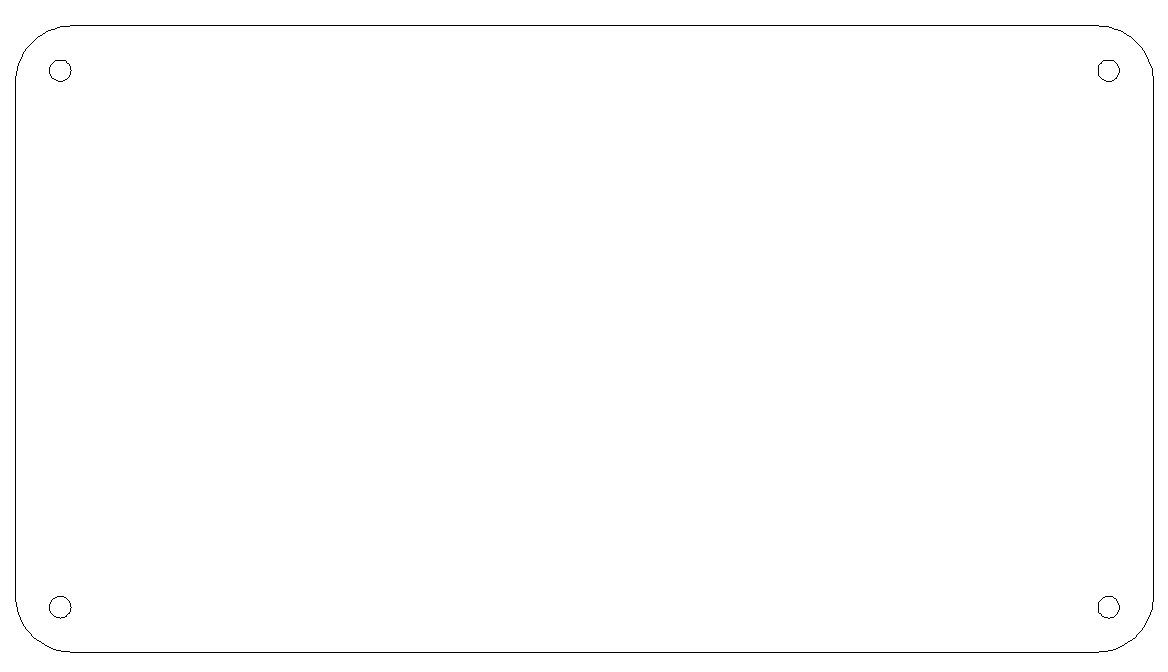
Front Panel (black and clear acrylic):
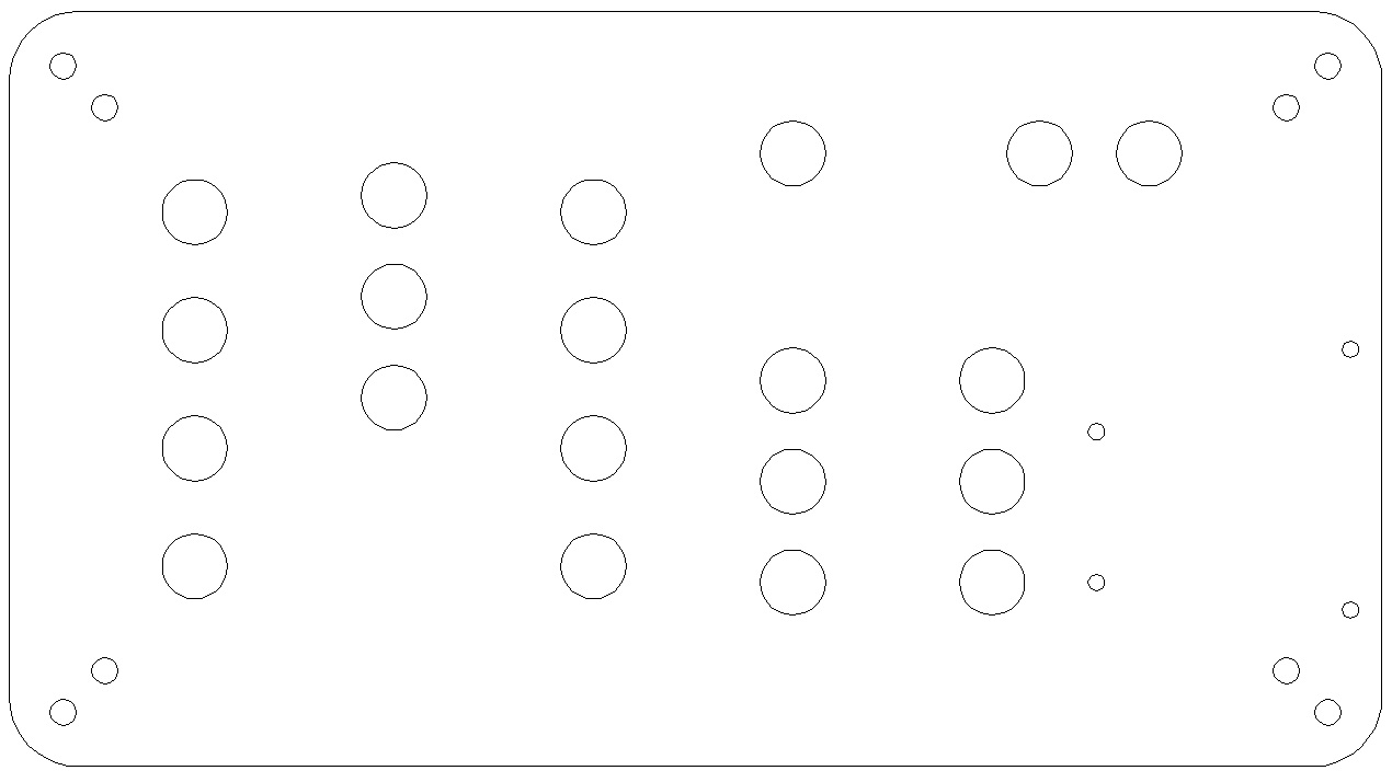
Middle Panel (clear acrylic):
Back Panel (black acrylic):

The Build Process
After laser cutting my parts out at my school, I was ready to put it all together.
Parts list:
- LED Chain
- Arduino Pro
- Bluetooth Shield
- Power Jack
- Toggle Switch
- 0.25” Black Acrylic
- 0.093” Clear Acrylic
- Rubber Feet
- 1” and 1.5” Spacers
- misc. Nuts and Bolts
- Lock Washers
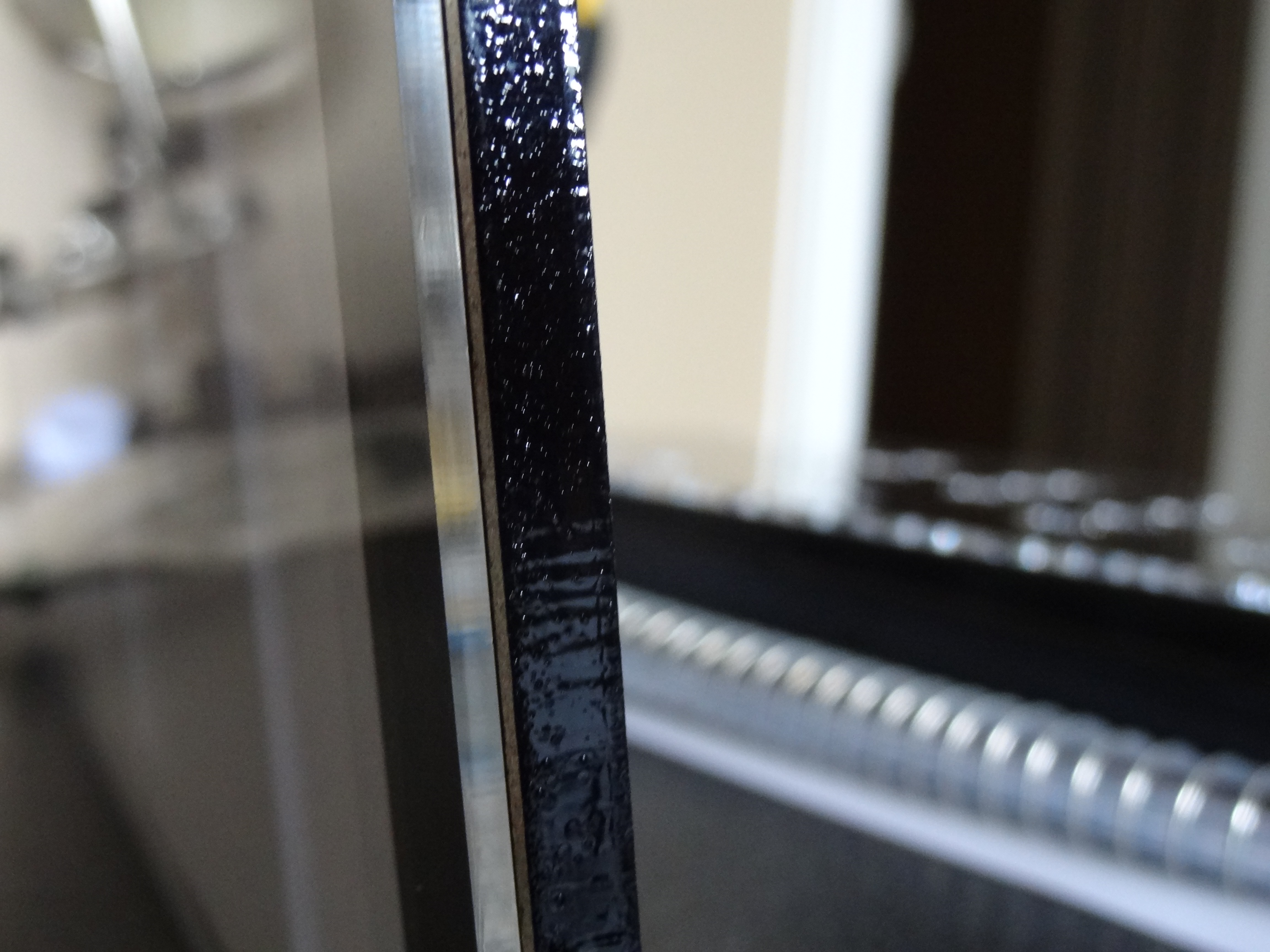
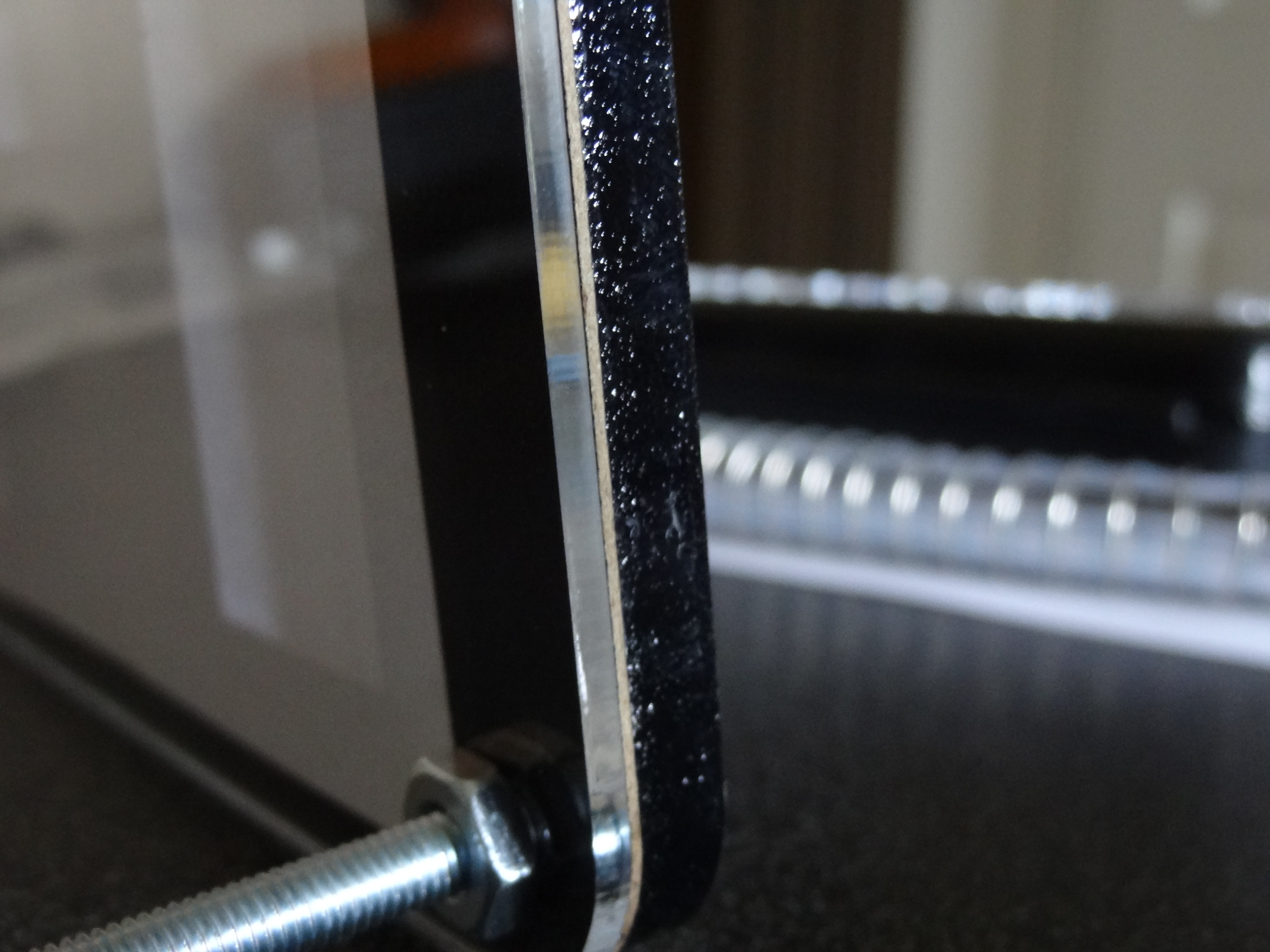
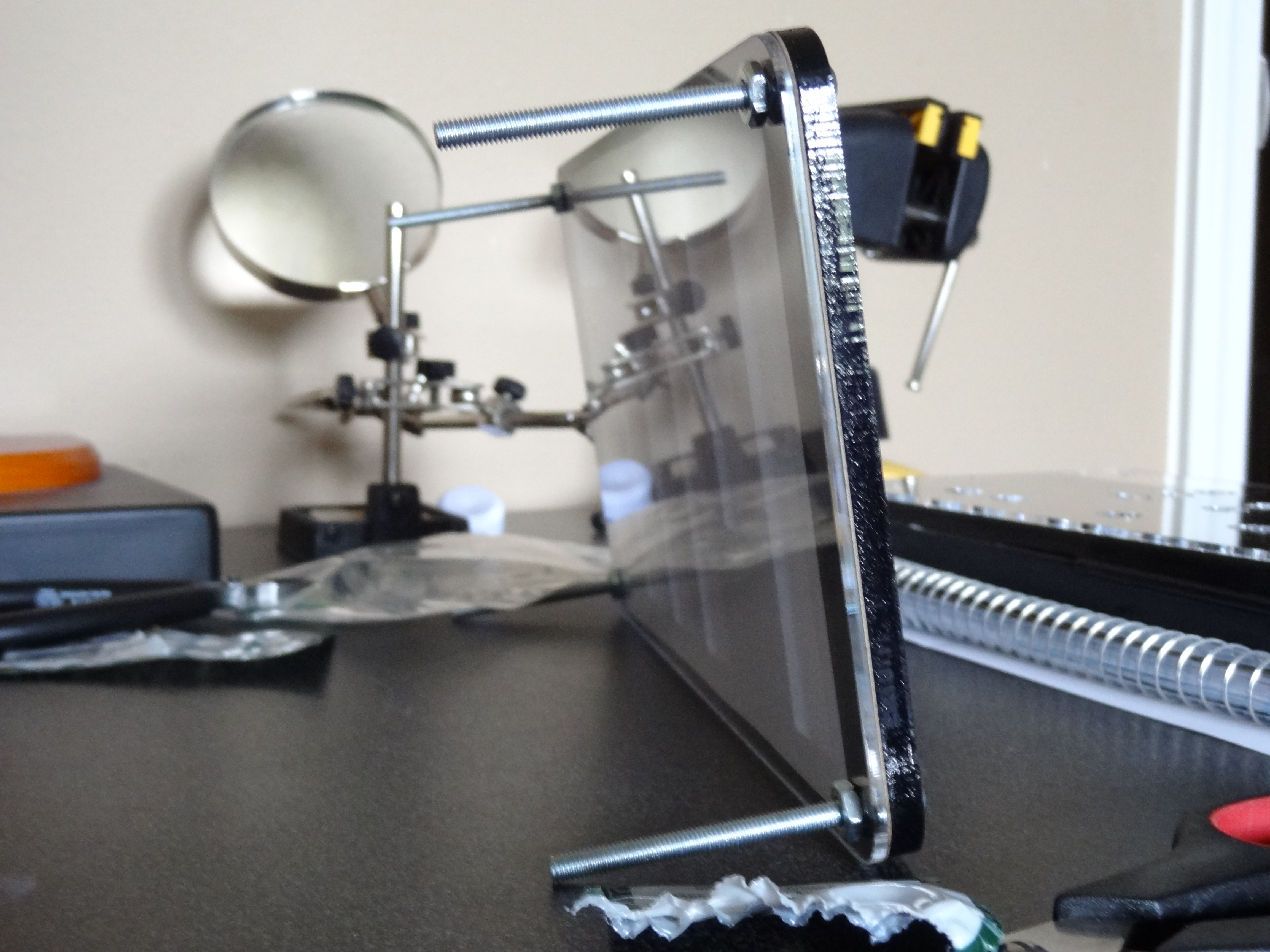
The front layer ended up a hair different from what I originally designed. It turns out my black acrylic was not opaque. You could see straight through it. That was going to be a problem because it needed to only allow light through the MIT logo. I solved that issue by adding a laser cut piece of black cardboard to the front layer. You can see the thin piece of cardboard in the photos below along with the black and clear acrylic and white paper.
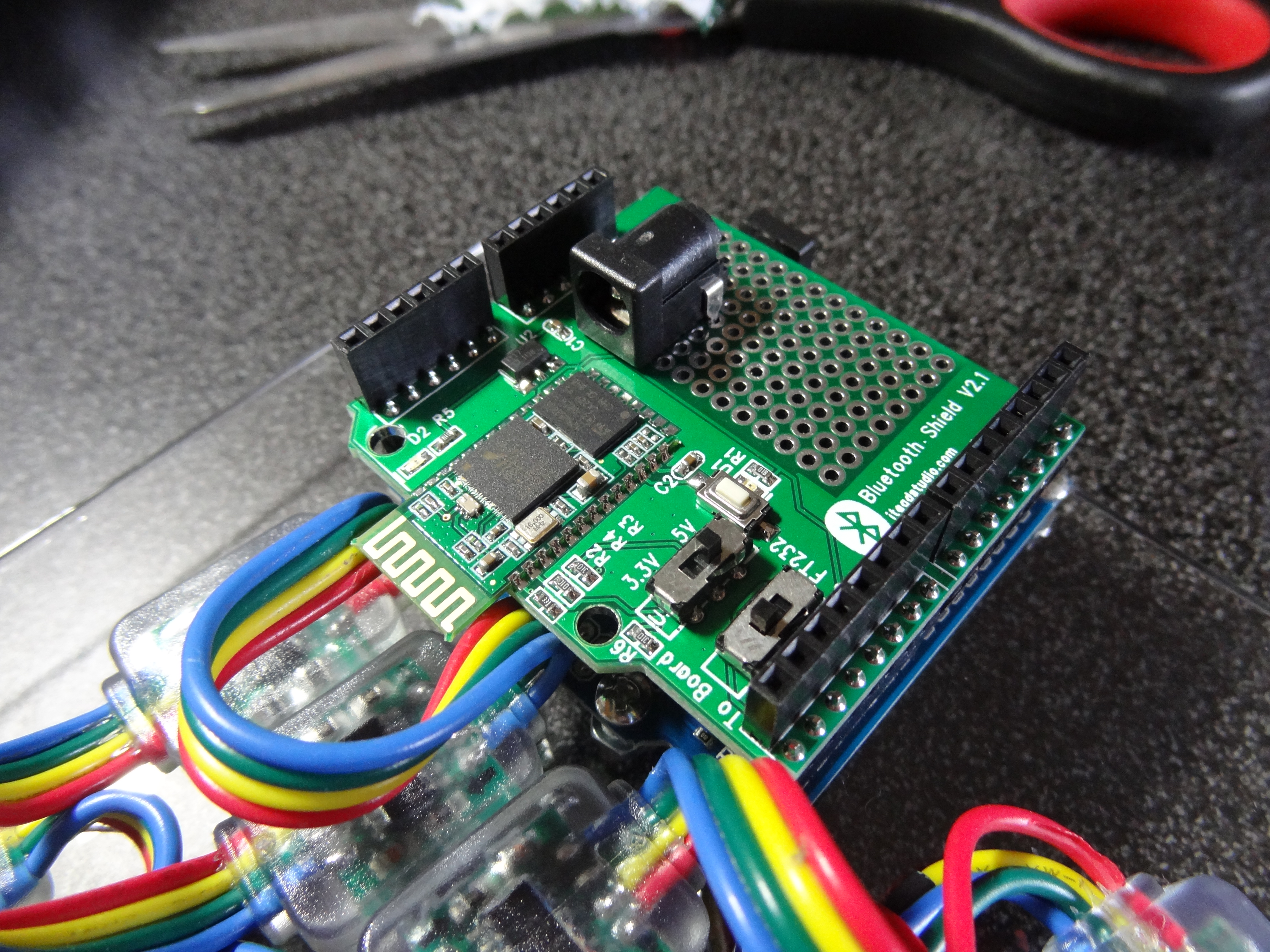
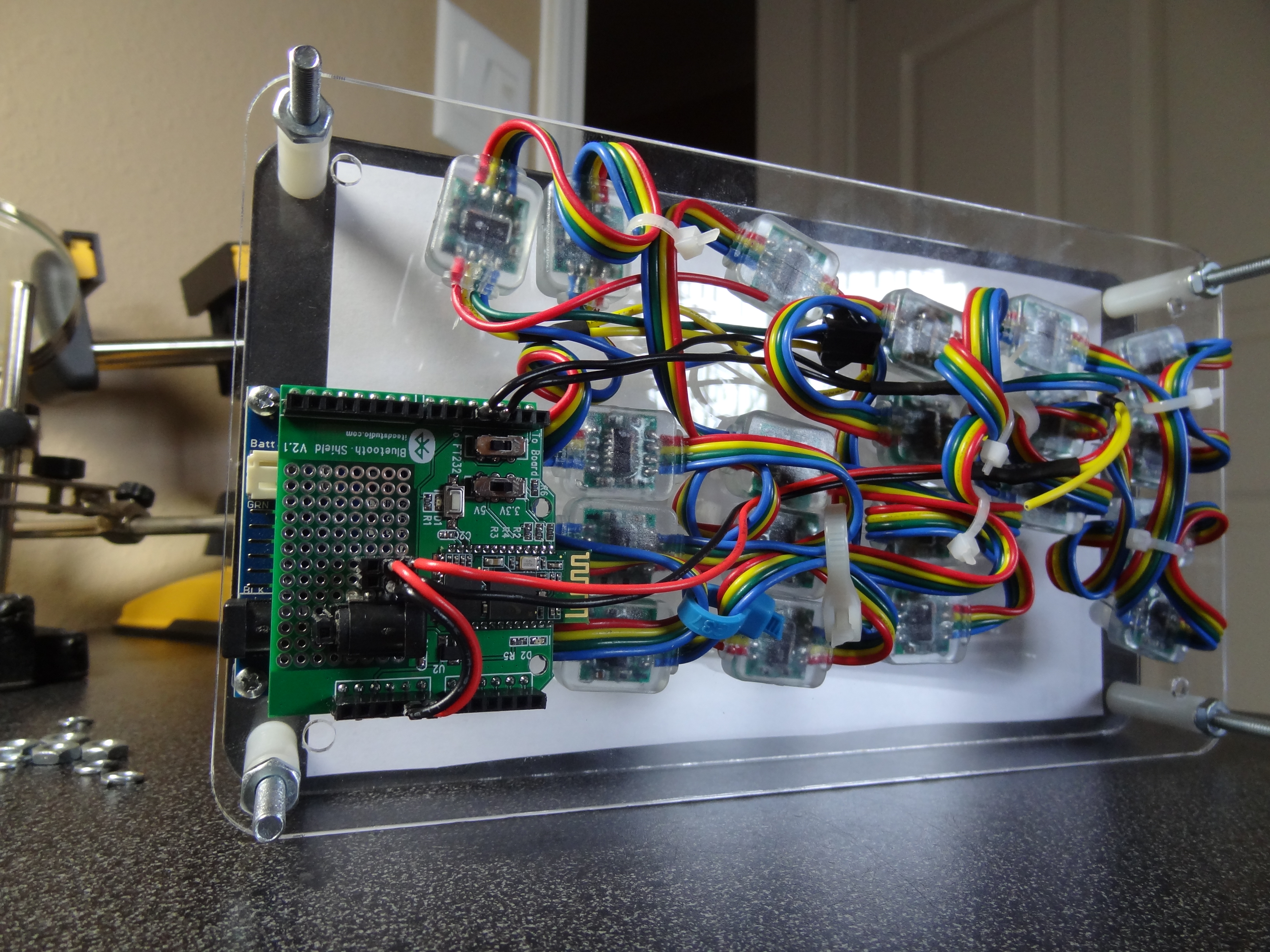
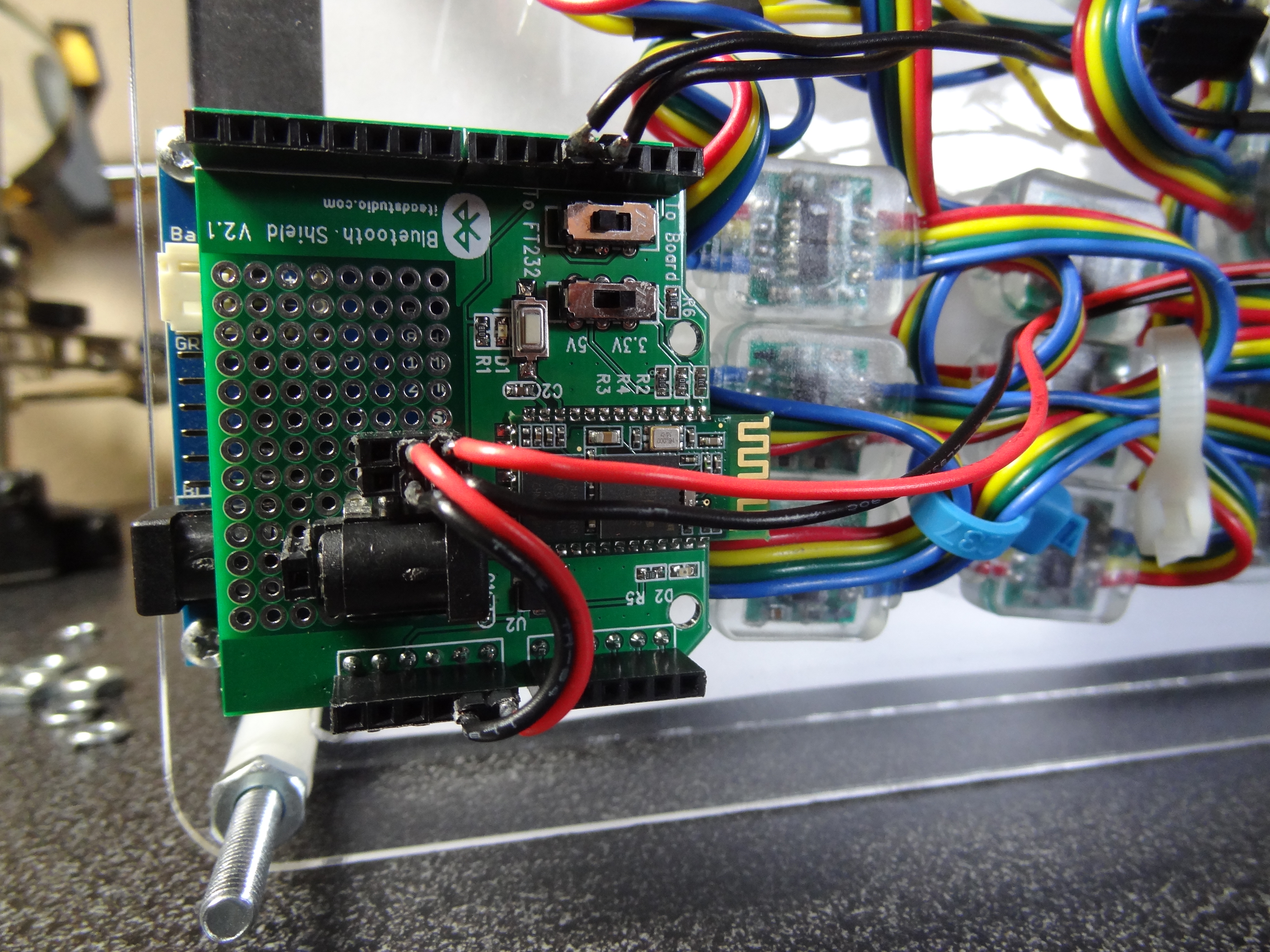
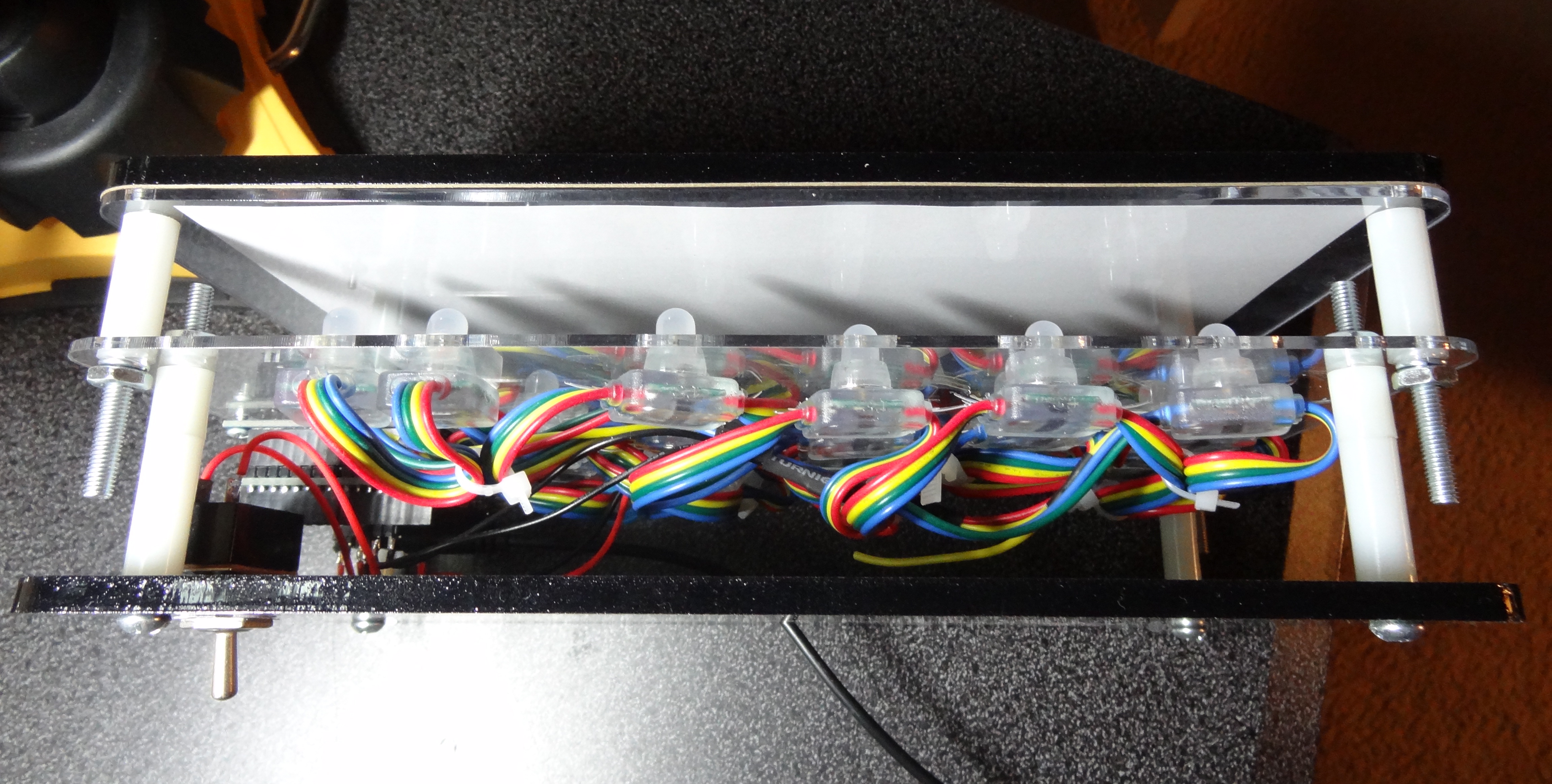
The LEDs fit snuggly in the large holes of the middle panel. The Arduino with the attached bluetooth shield bolts onto the middle panel near the right edge. This placement of the micro-controller allows the programming cable to easily be plugged in.
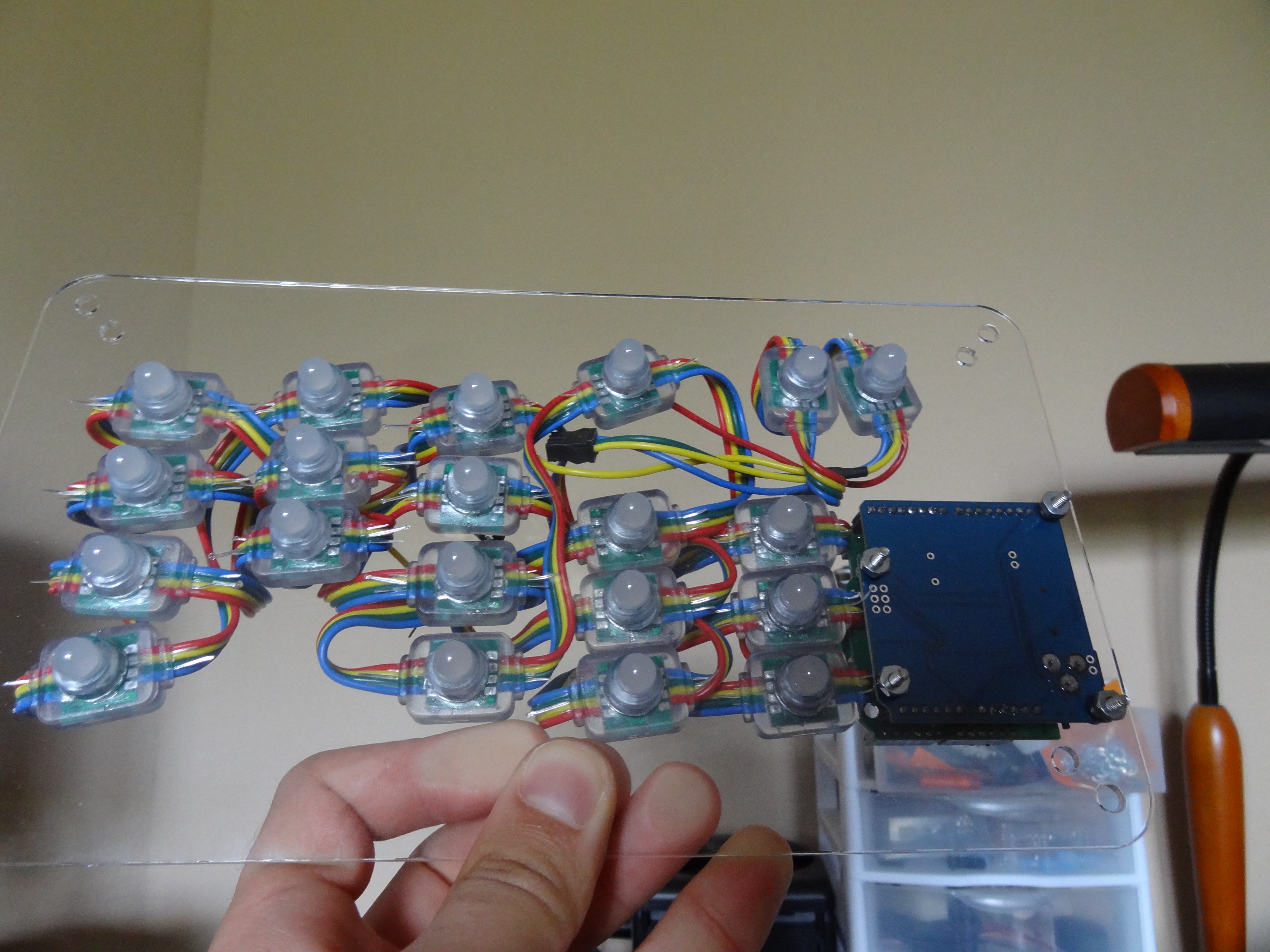
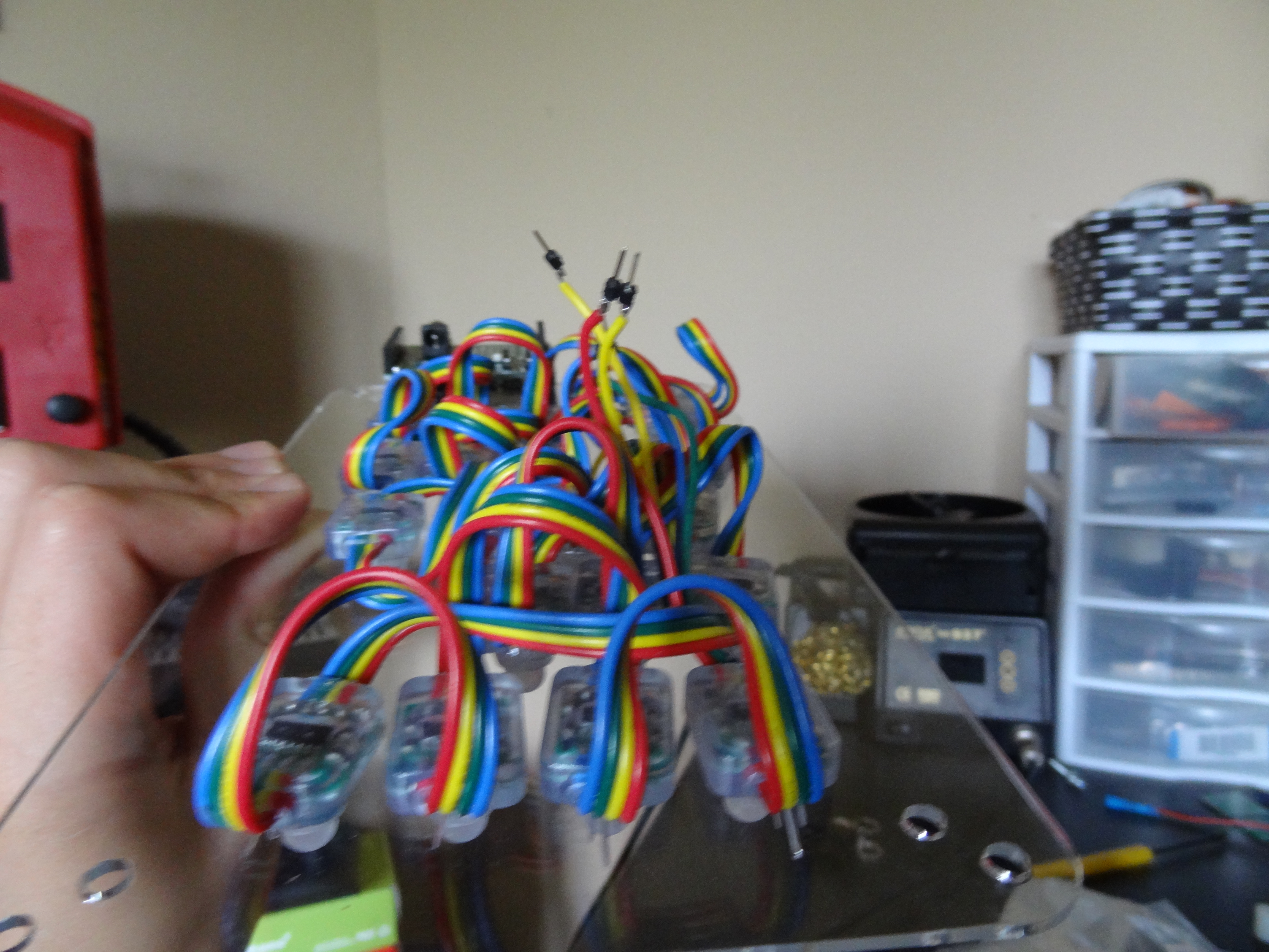

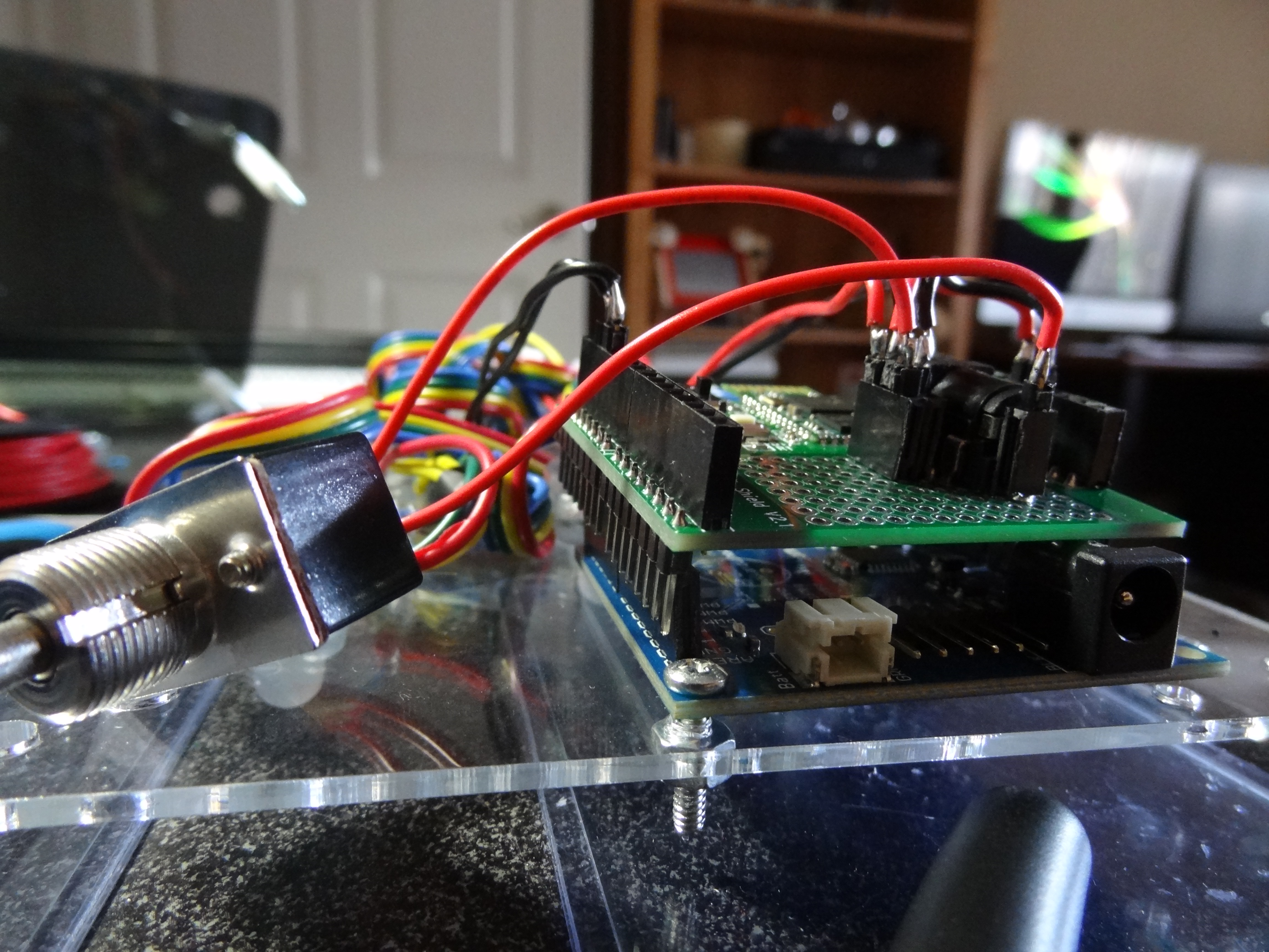
The bluetooth shield has a prototyping area that I used for power distribution. This is also where the power jack is located. You can see the power jack faces towards the middle of the sign. This allows the power cable to come out of the back of the sign like I had planned.
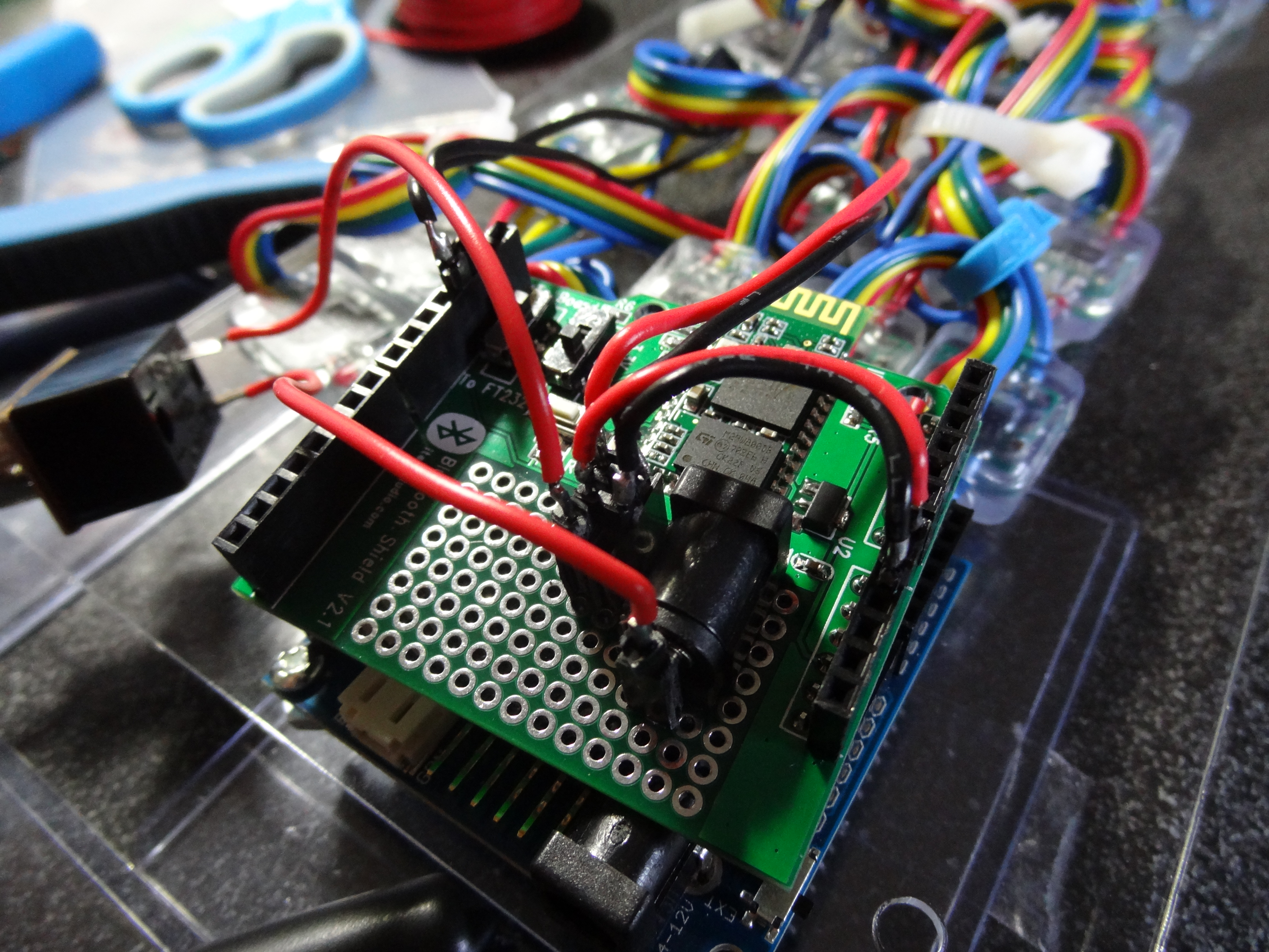
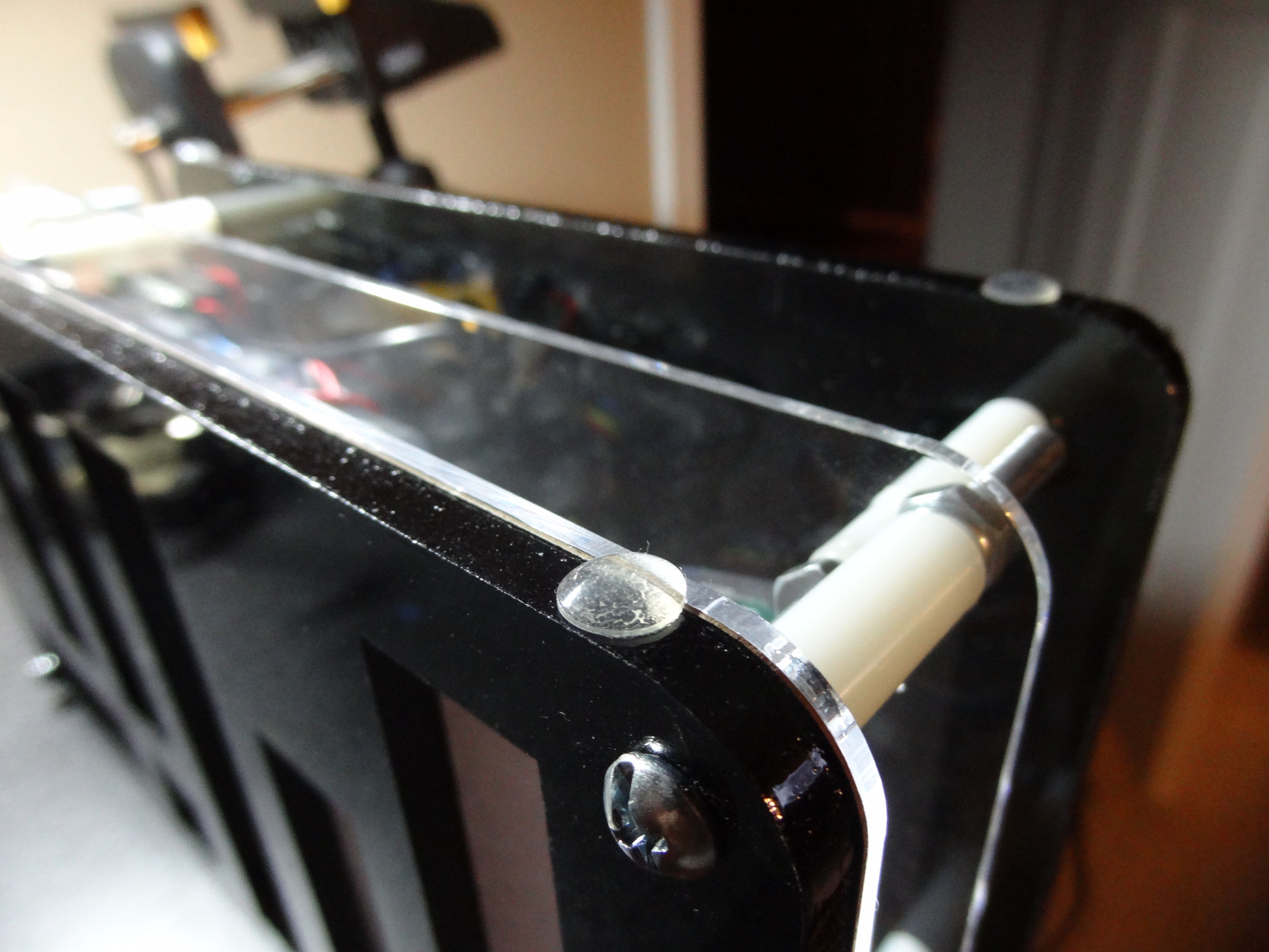
I used zip-ties to compact the LED wiring and then bolted the middle panel onto the front panel.
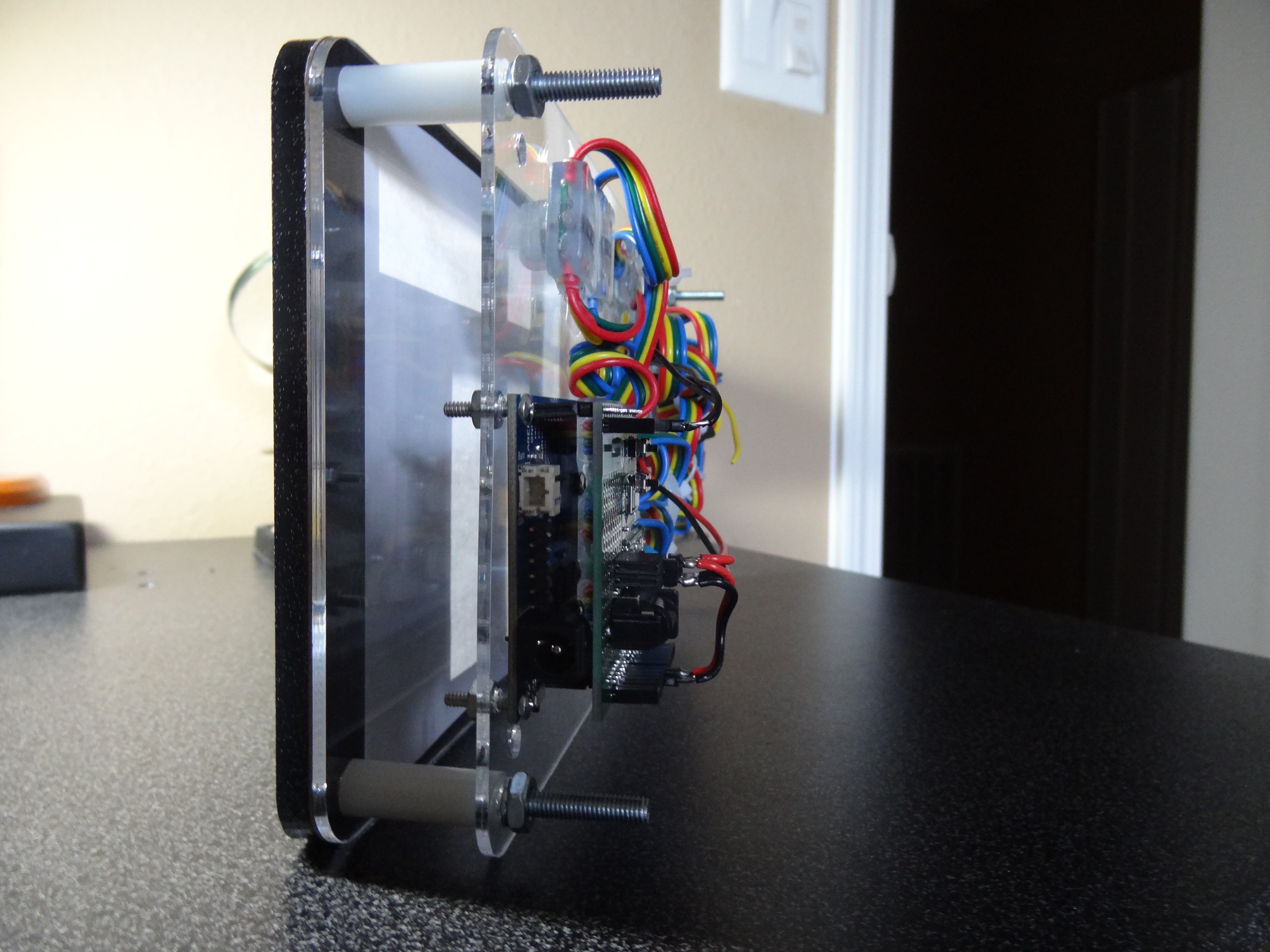
Next, the back panel was bolted on, the power switch was attached, and the power cable was plugged in.
Lastly, I attached the rubber feet to the four bottom corners of the sign. That concludes the build process.
The Computer Software
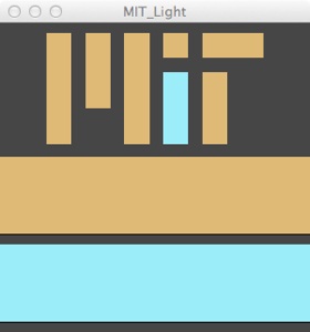
The purpose of the computer software (written in Processing) is to update the sign’s colors. On the MIT website there is a logo in the upper left hand corner. They change the color of this logo every day. By simply right clicking and choosing “Copy Image URL” I obtained the URL to that logo.
Using the URL, the program is able to create an image object. The program then extracts the two different colors in the logo. One is called the “majority” color and the other is the “minority.” In the image above, the majority color is tan and the minority is blue. It does this by breaking apart two different pixels into their RGB components. The majority color can be found at the first pixel of the image and the minority color is found at pixel #1141 (this is not the first occurrence of the minority color, it is just the one I chose to use). Using a serial connection, it sends these bytes over bluetooth to the sign, which then updates itself.
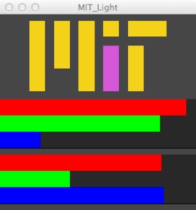
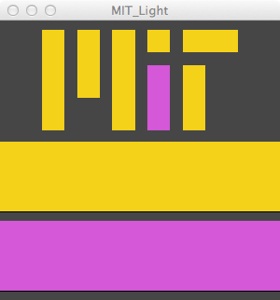
The logo image is displayed in the program’s window. It is scaled up so it is easier to see. The major and minor colors are also displayed as two rectangles below the image. When the user mouses over these rectangles they break up into 3 separate RGB bars. The length of these bars are mapped (i.e. scaled) to the RGB value they represent.
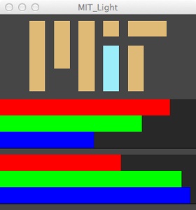
The RGB bars can also be used as adjustment sliders. So if the user wants to change the color of the sign manually then they can adjust the color of the logo by clicking on and dragging the RGB bars. The user can then update the light by right clicking their mouse, which will send the new RGB values over bluetooth to the sign.
Click here to download the full program. This version includes the serial communication code and WILL NOT run unless you connect it to a serial port by modifying the code.
Click here to download a partial version. This version does not include the serial communication code and WILL run without modification.