Pong
Intro
Click here to download my files for this project. That includes my Arduino code and my custom PCB Eagle CAD files. Click here to view the code without downloading.
Do you remember spending your childhood playing Pong? Neither do I, but why not bring it back? So here is my attempt to bring it back...
Constructing The Display
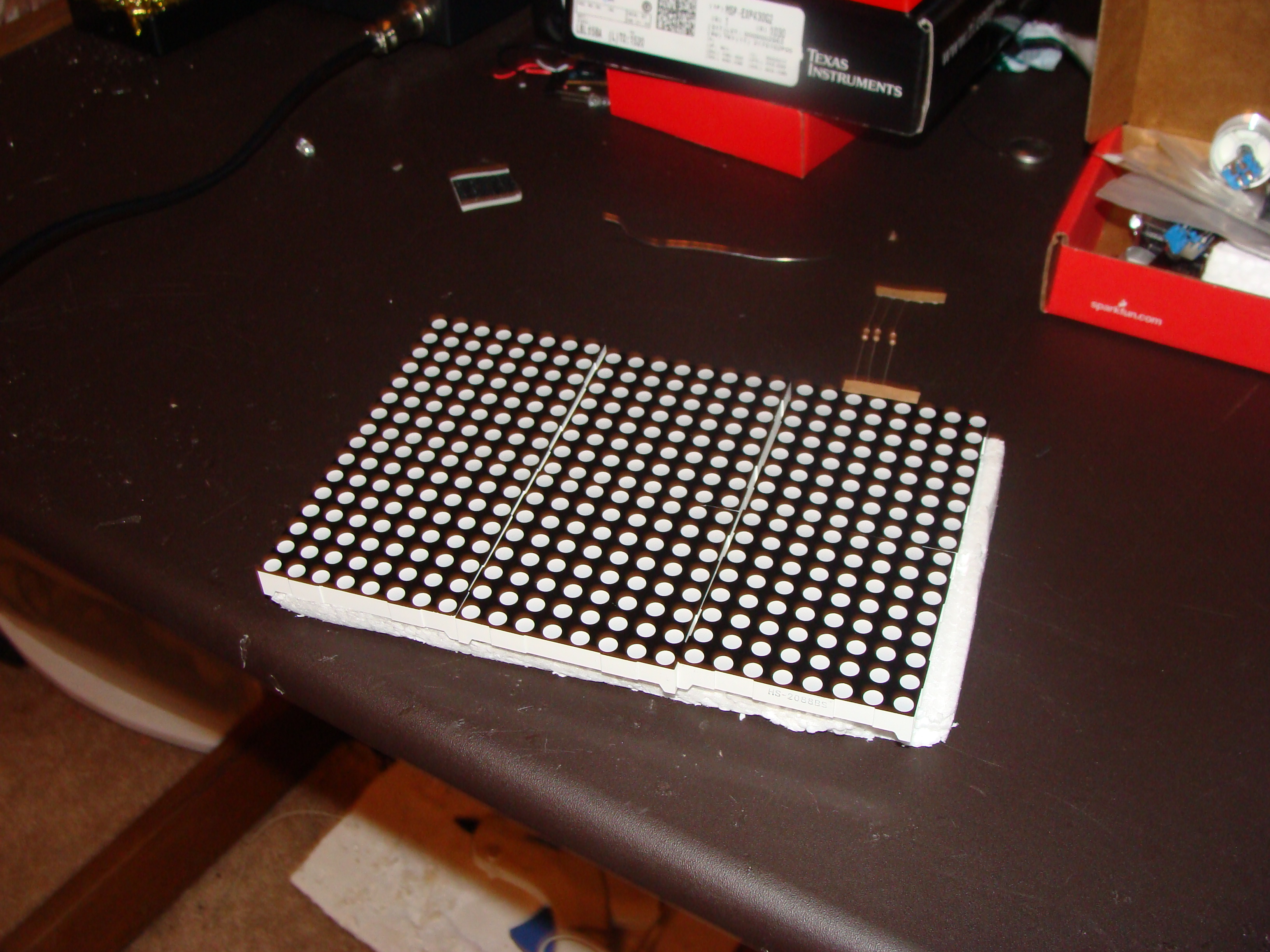
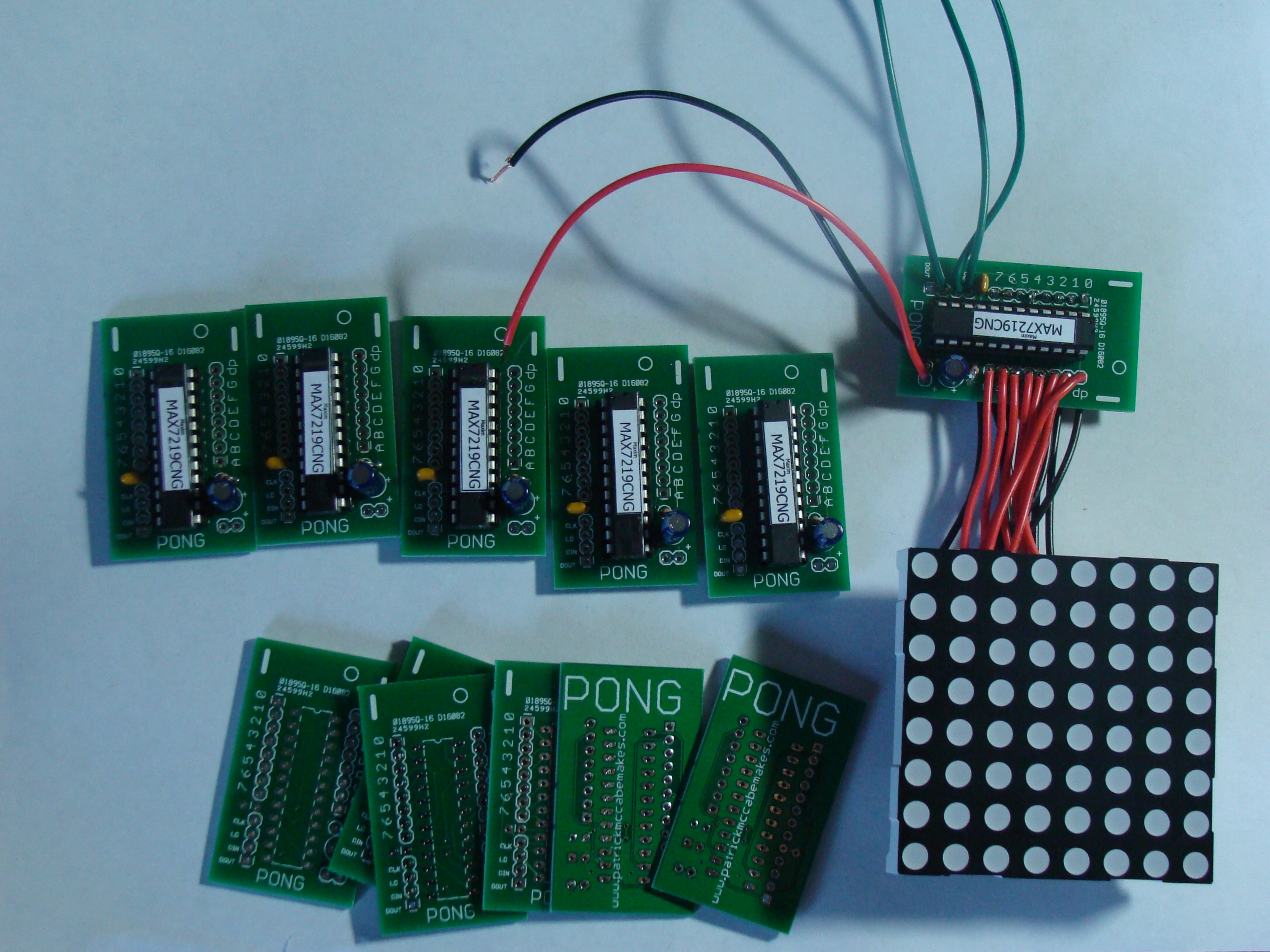
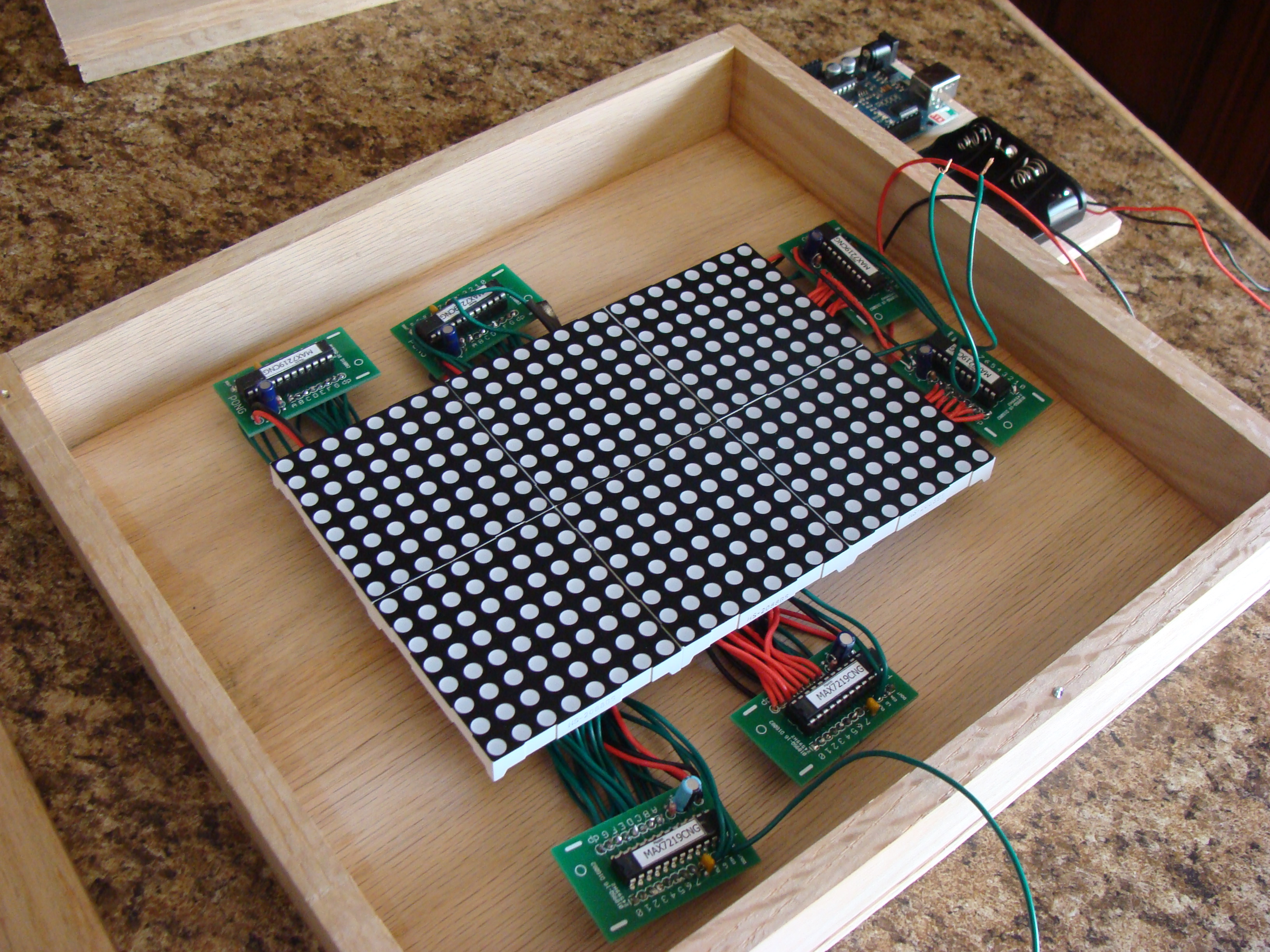
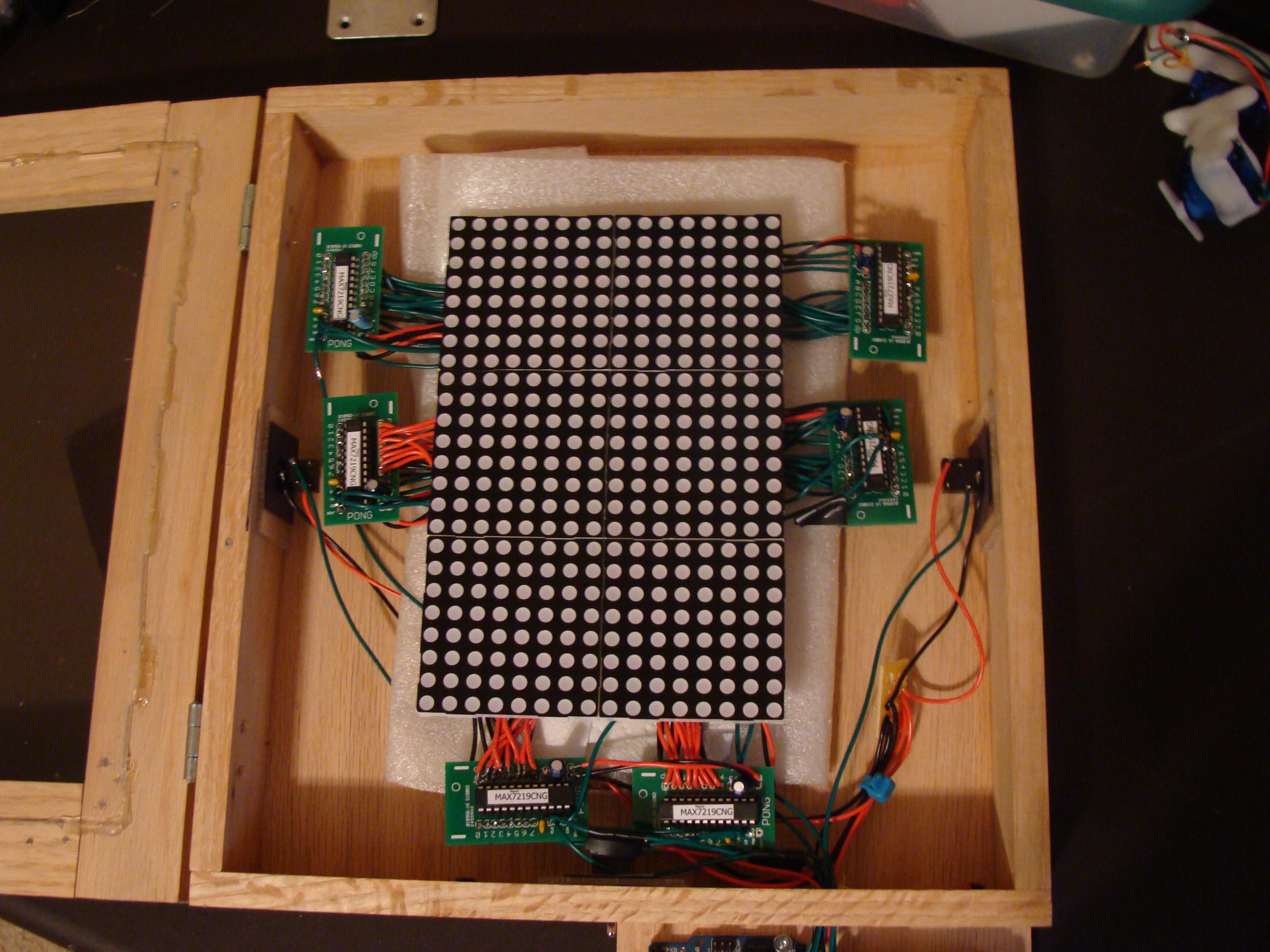
The display will consist of siz 8x8 LED matrices. The matrices are form eBay. They were about $11 total.
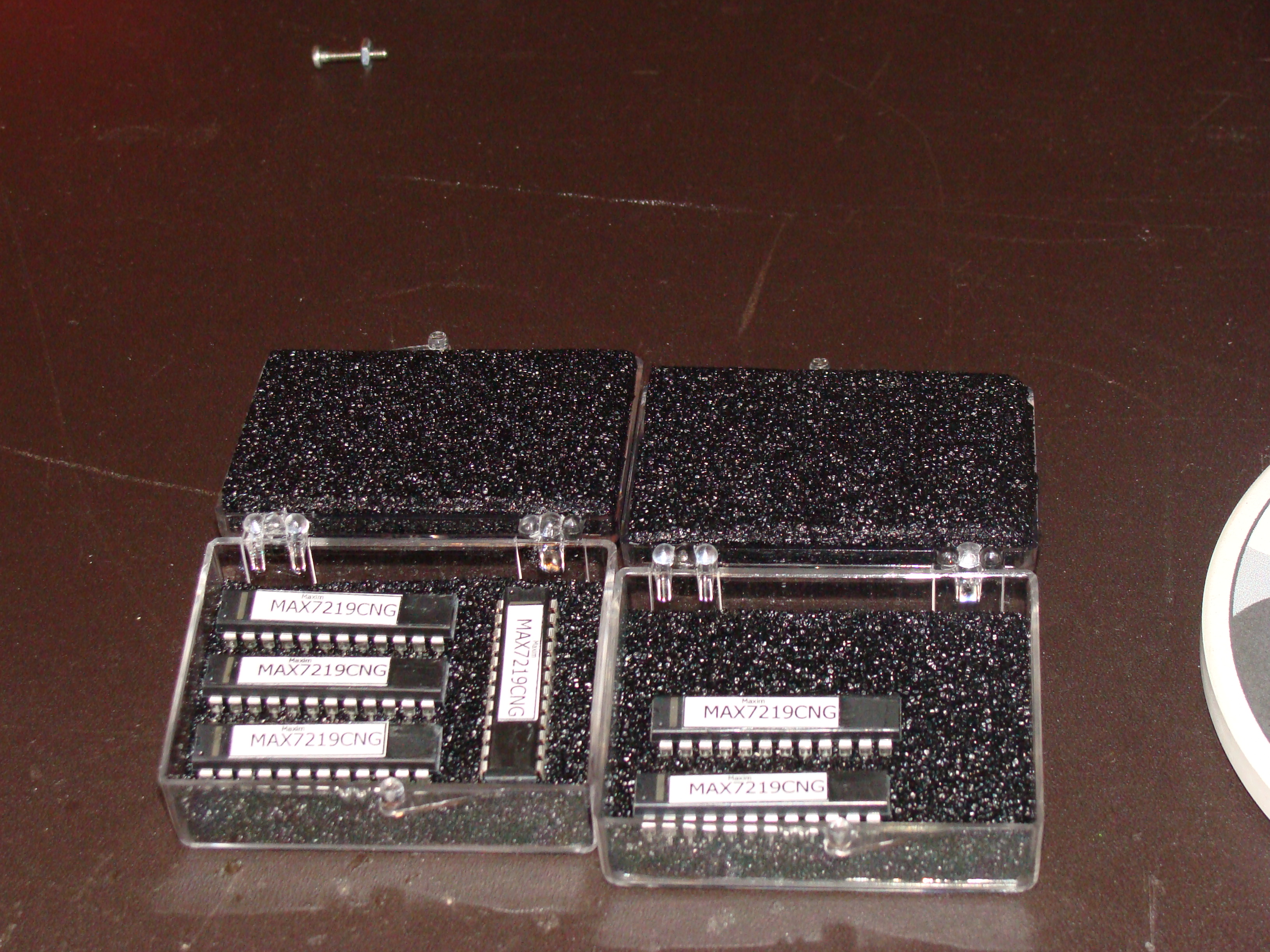
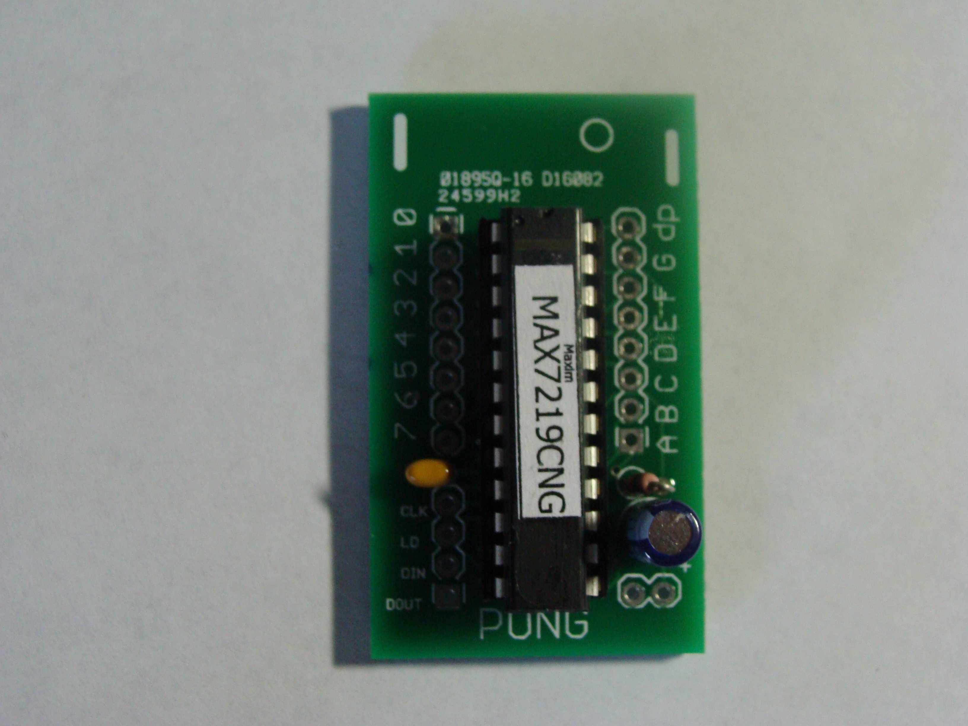
The MAX7219CNG is a LED matrix driver IC from Maxim. They make life a little easier and have some different power saving settings. A very nice guy gave me these. They retail for $10 or so.
I designed some custom PCBs for the LED driver. I used Seeedstudio again because I think they are the best fab house when it comes to price. They give you 10 PCBs for $20. They actually sent me 12 PCBs this time - thats about $1.70 a PCB! My design only requires 6 of them.
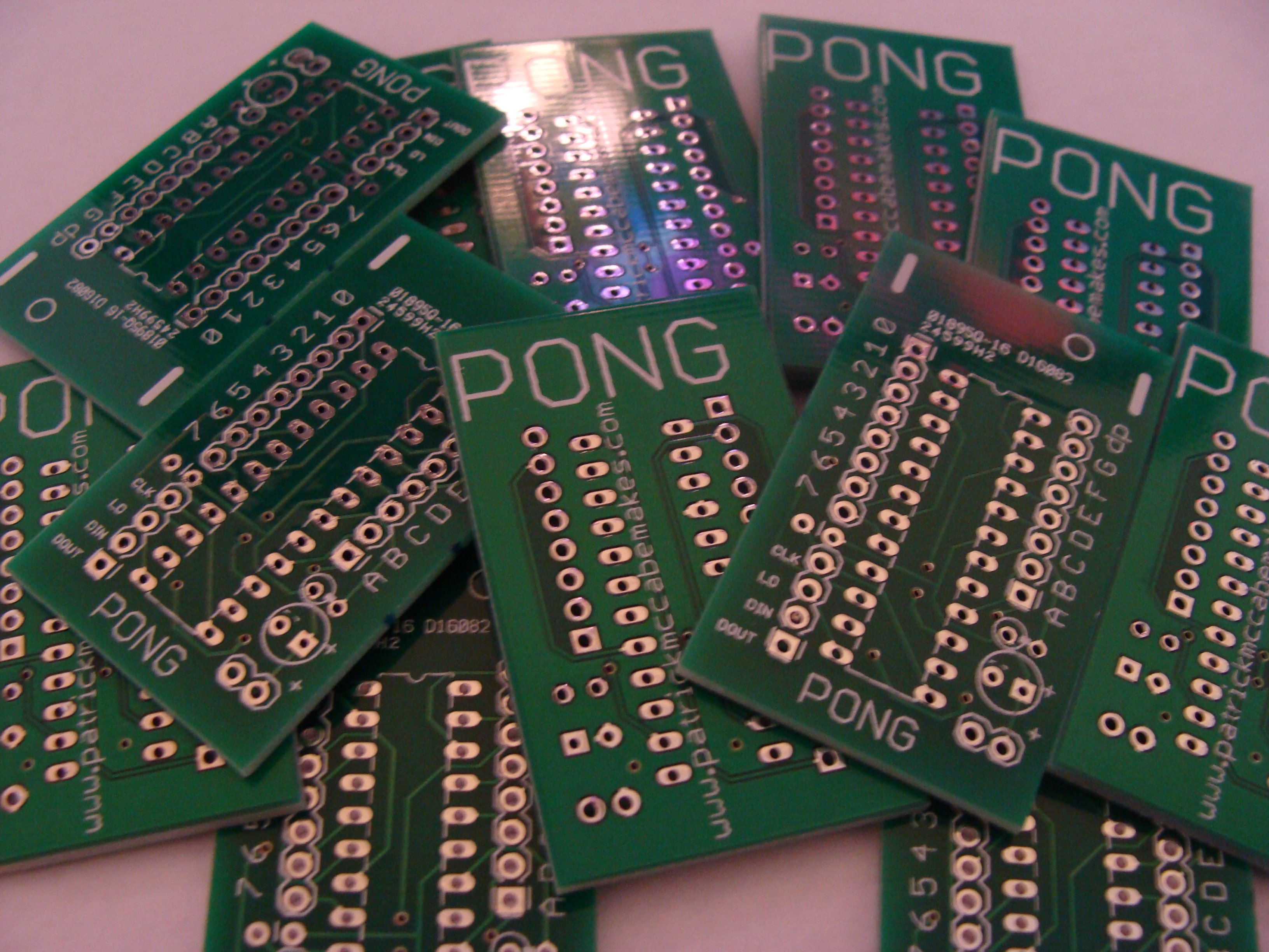
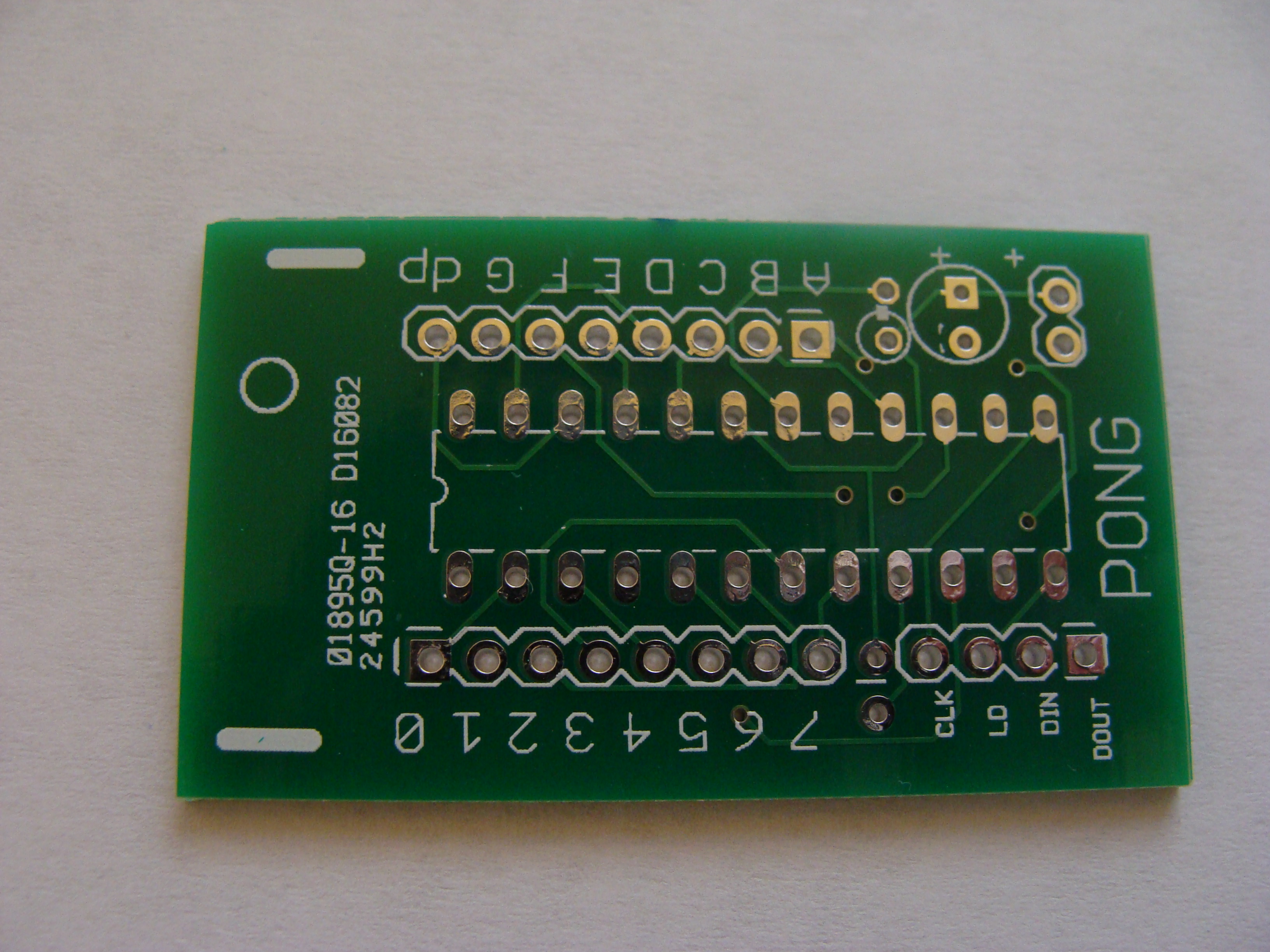
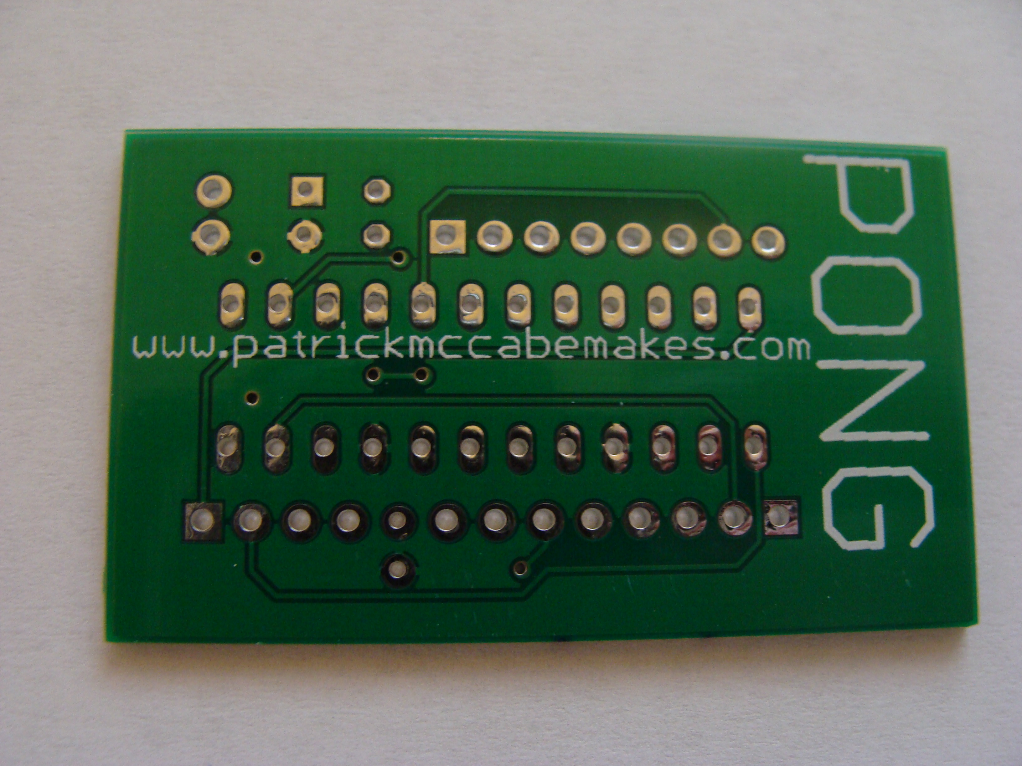
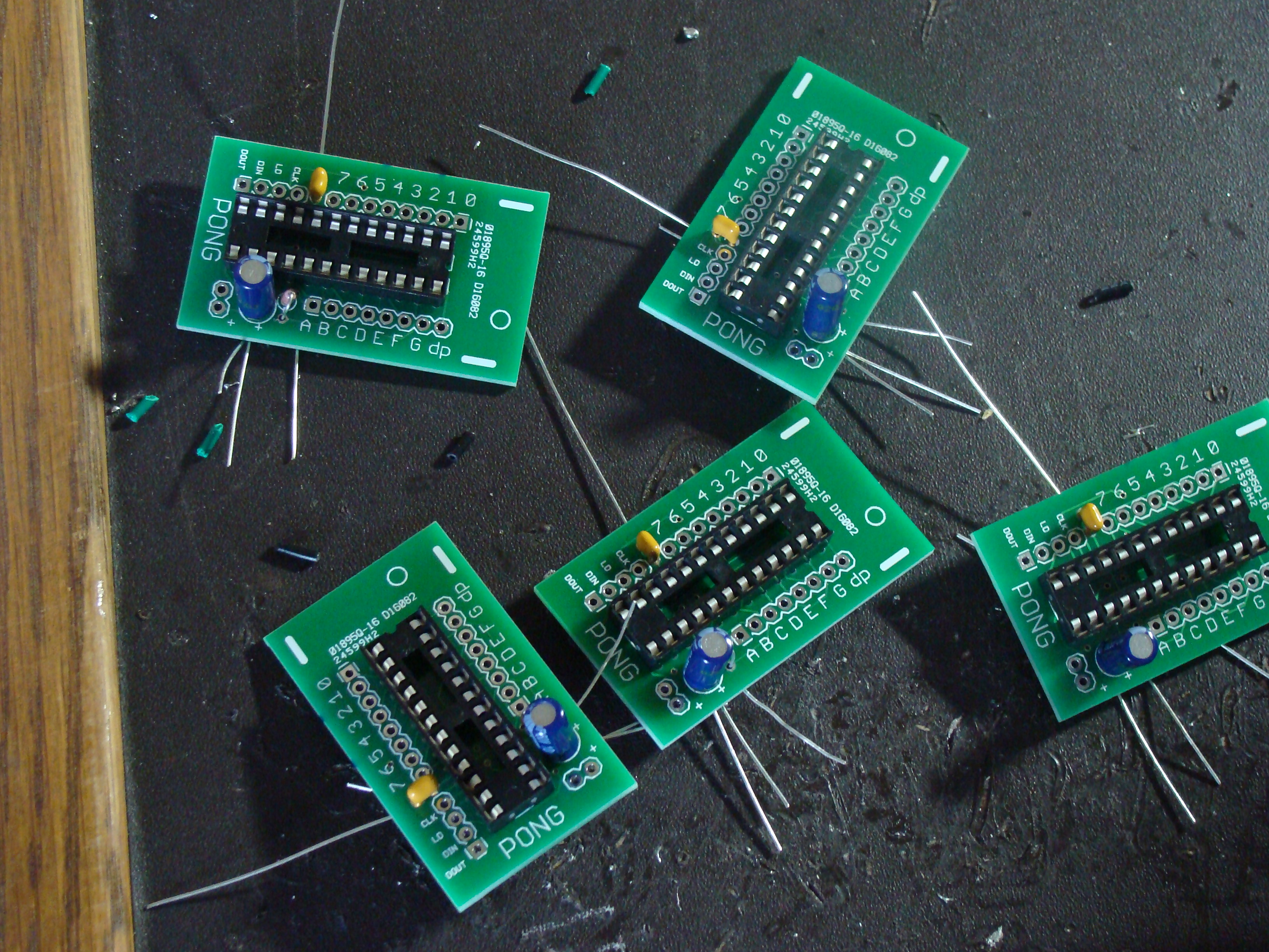
The circuit boards have 2 capacitors, a 1k resistor, which sets the current limit for the LEDs, and a socket for the MAX7219CNG.
I made a processing sketch that communicates with my Arduino over serial. If I click one of the squares on the processing sketch, then that square turns red and the corresponding LED on the matrix lights up. When I have the whole pong screen constructed, I will make a processing programming for the display so I can design animations and have it give me the code for it.

The processing sketch outputs the code for the pattern on the LED matrix. It gives the array that stores the binary data to light up each row to display the image.
Constructing The Paddles
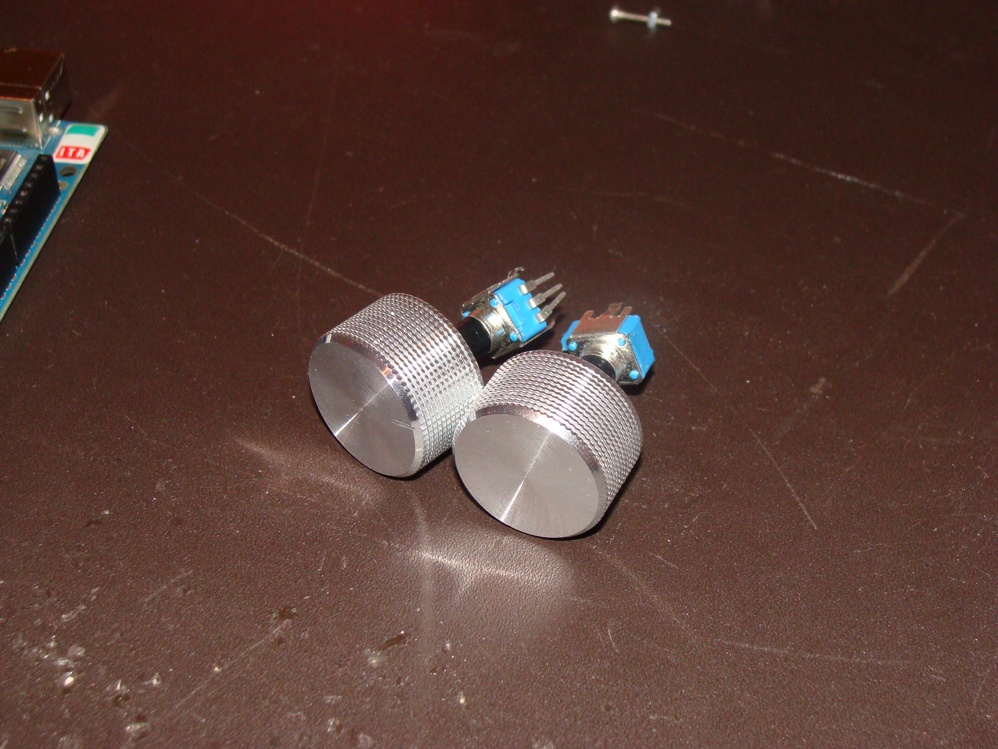
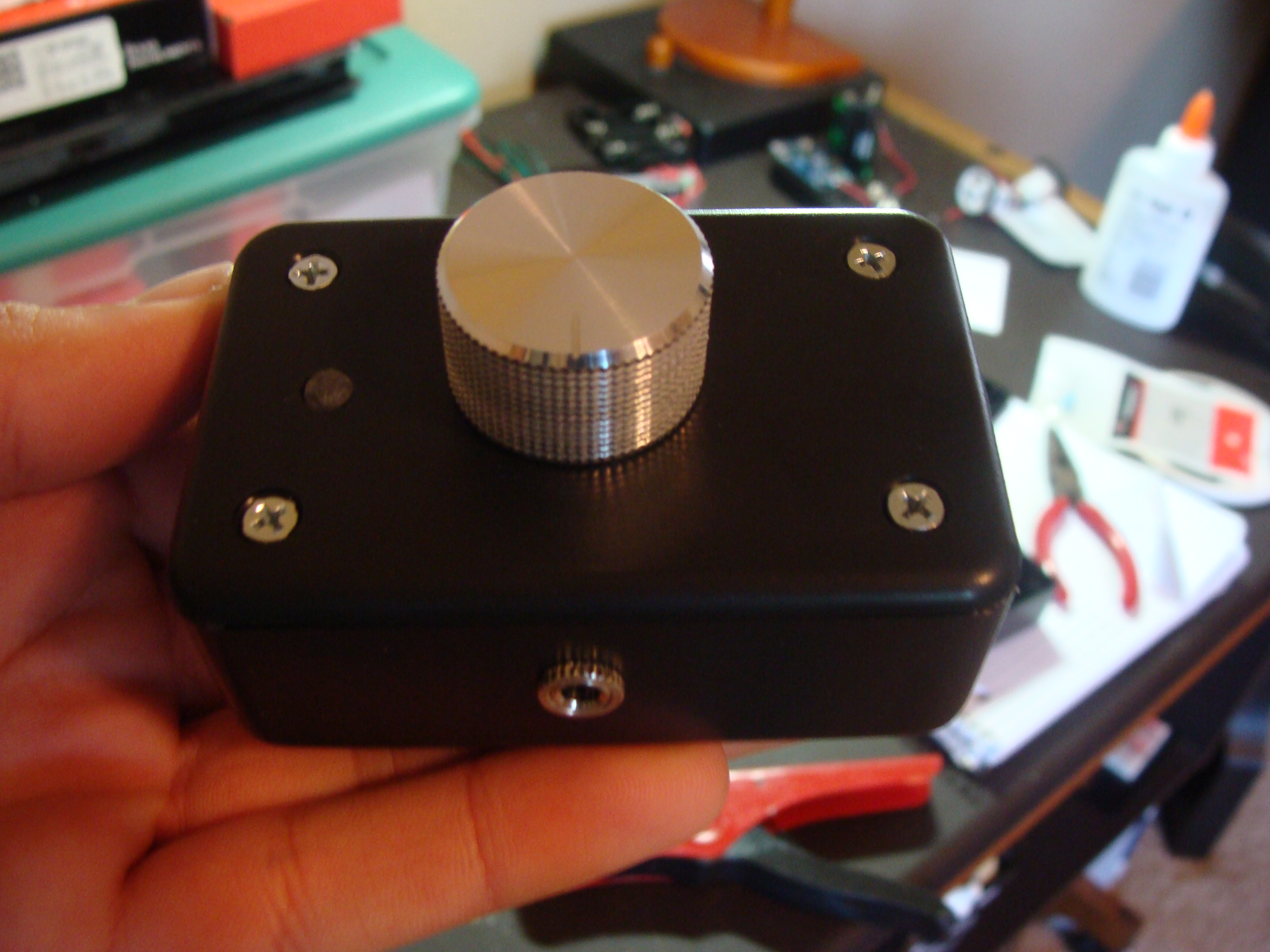
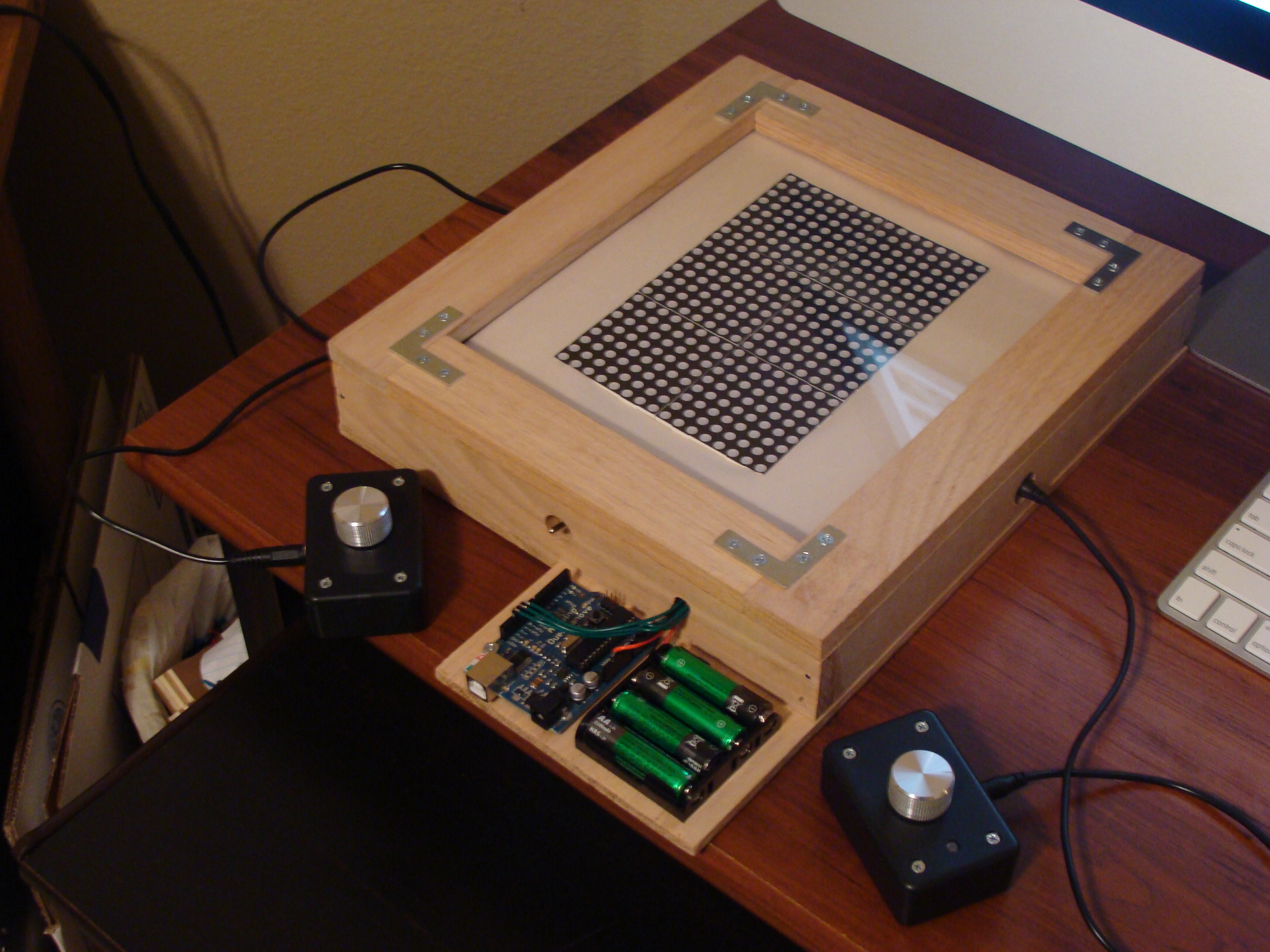
Can you have pong without a good set of knobs? These knobs are from Sparkfun. The knobs sit on top of a potentiometer, which sends out an analog voltage when turned. This voltage can be read by the microcontroller which then makes decisions based off of it.
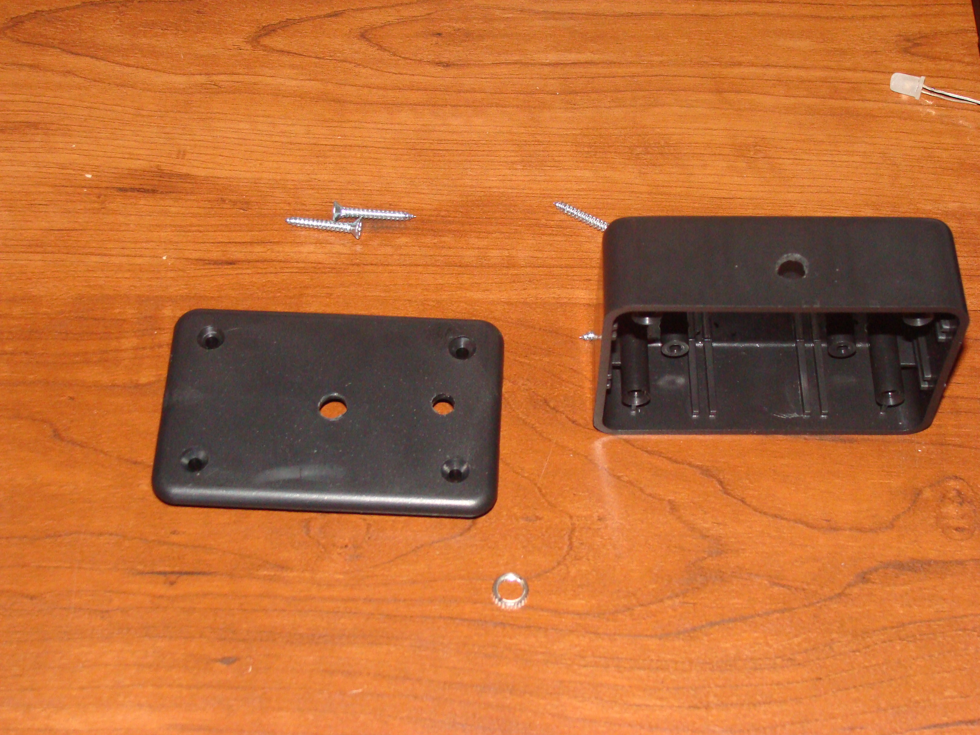
I went to Radio Shack to get the rest of the parts that would be needed for the pong paddles. The paddles are made with a 3”x2”x1” ABS plastic project box. This box holds the audio jack (I am using an audio jack as a plug. No audio is being sent through this cable), potentiometer, LED, and hides all the wires. There will be matching audio jacks on the pong screen.
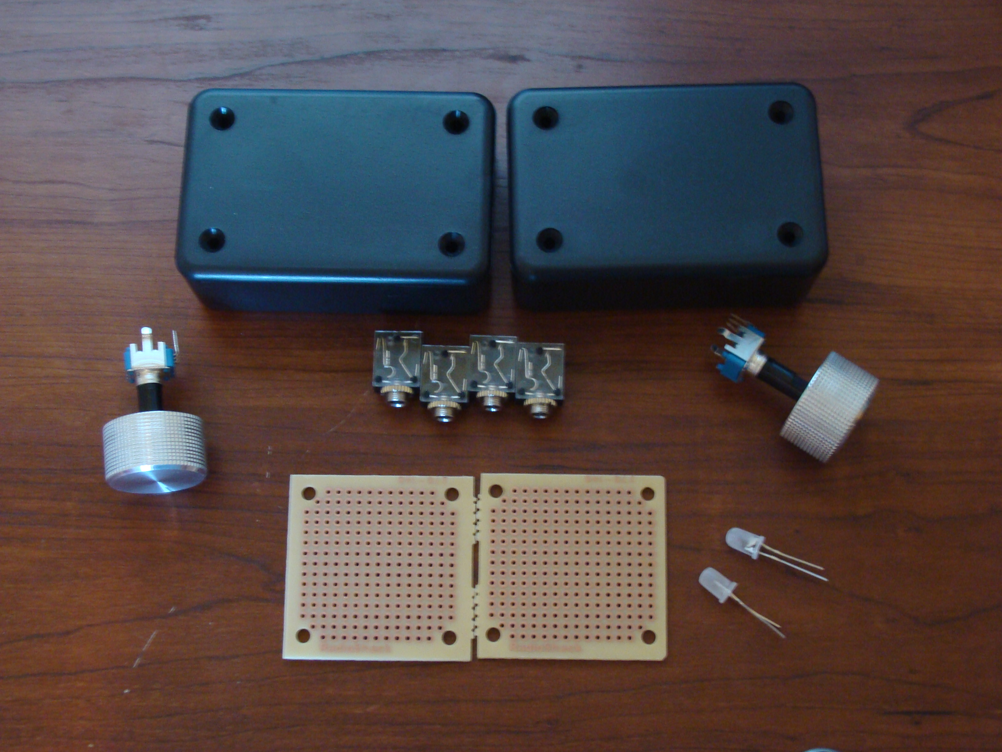
3 holes had to be drilled in the project box: one each for the potentiometer, LED, and audio jack.
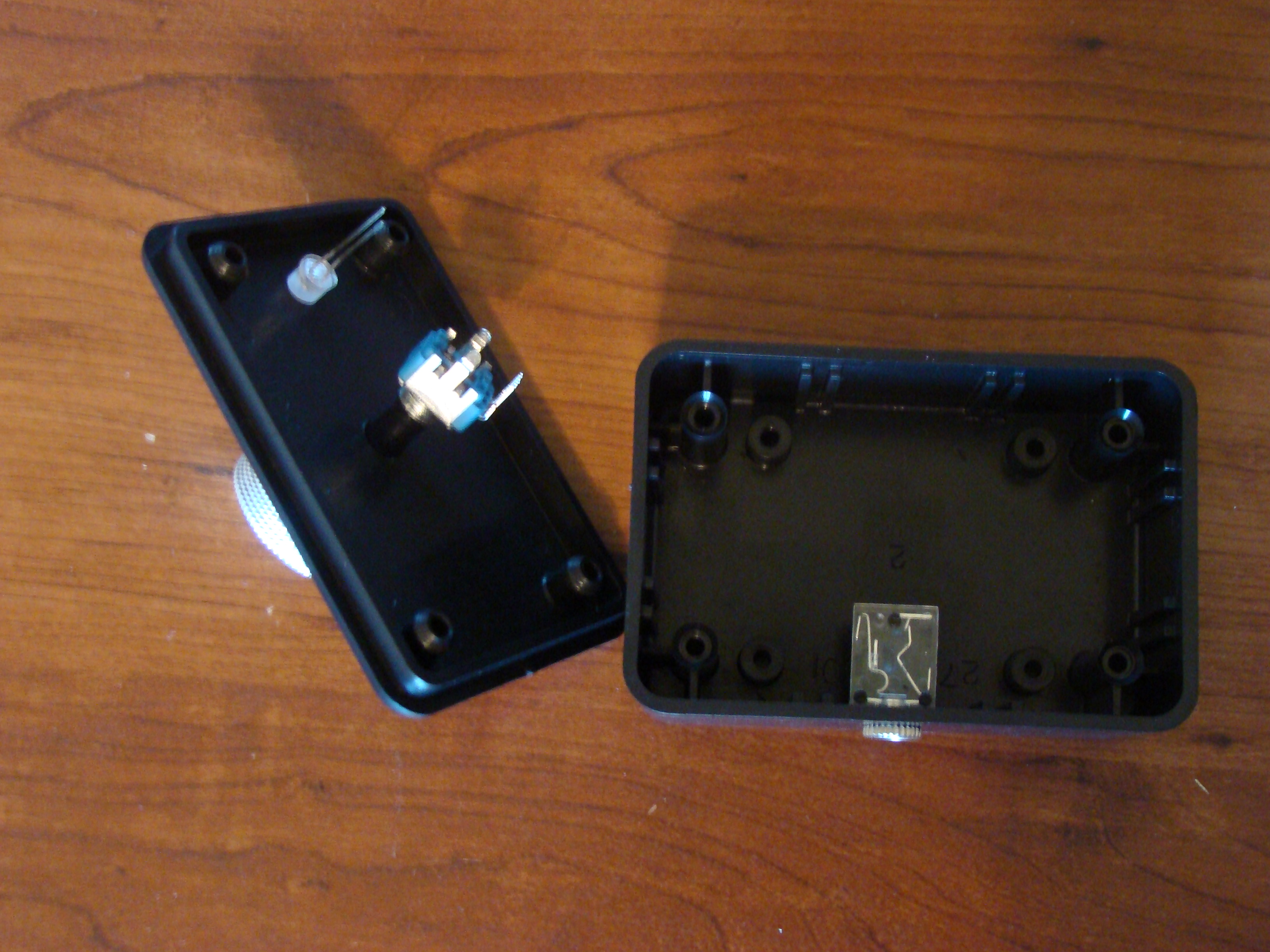
The respective connections are made between the potentiometer and audio jack.
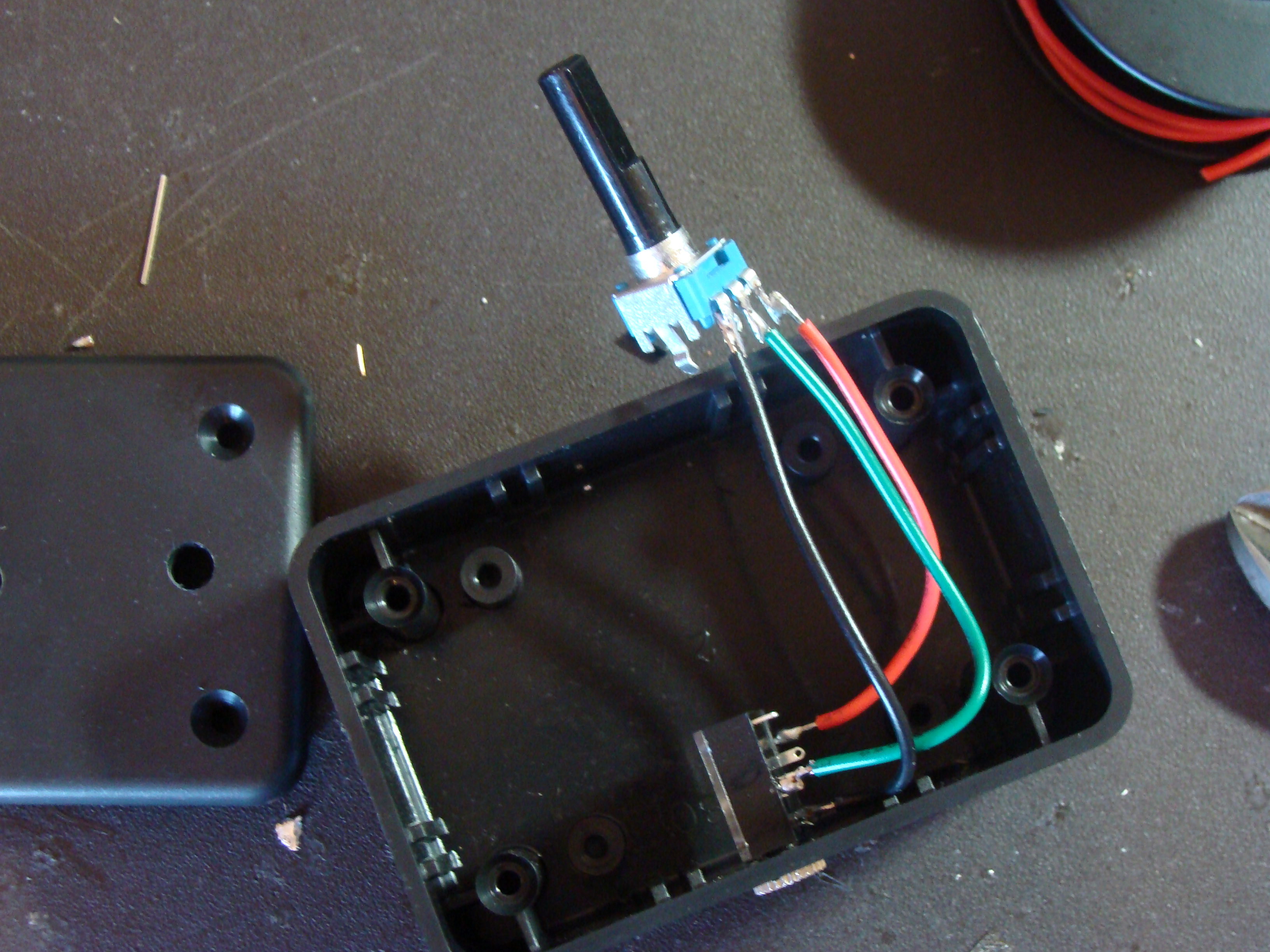
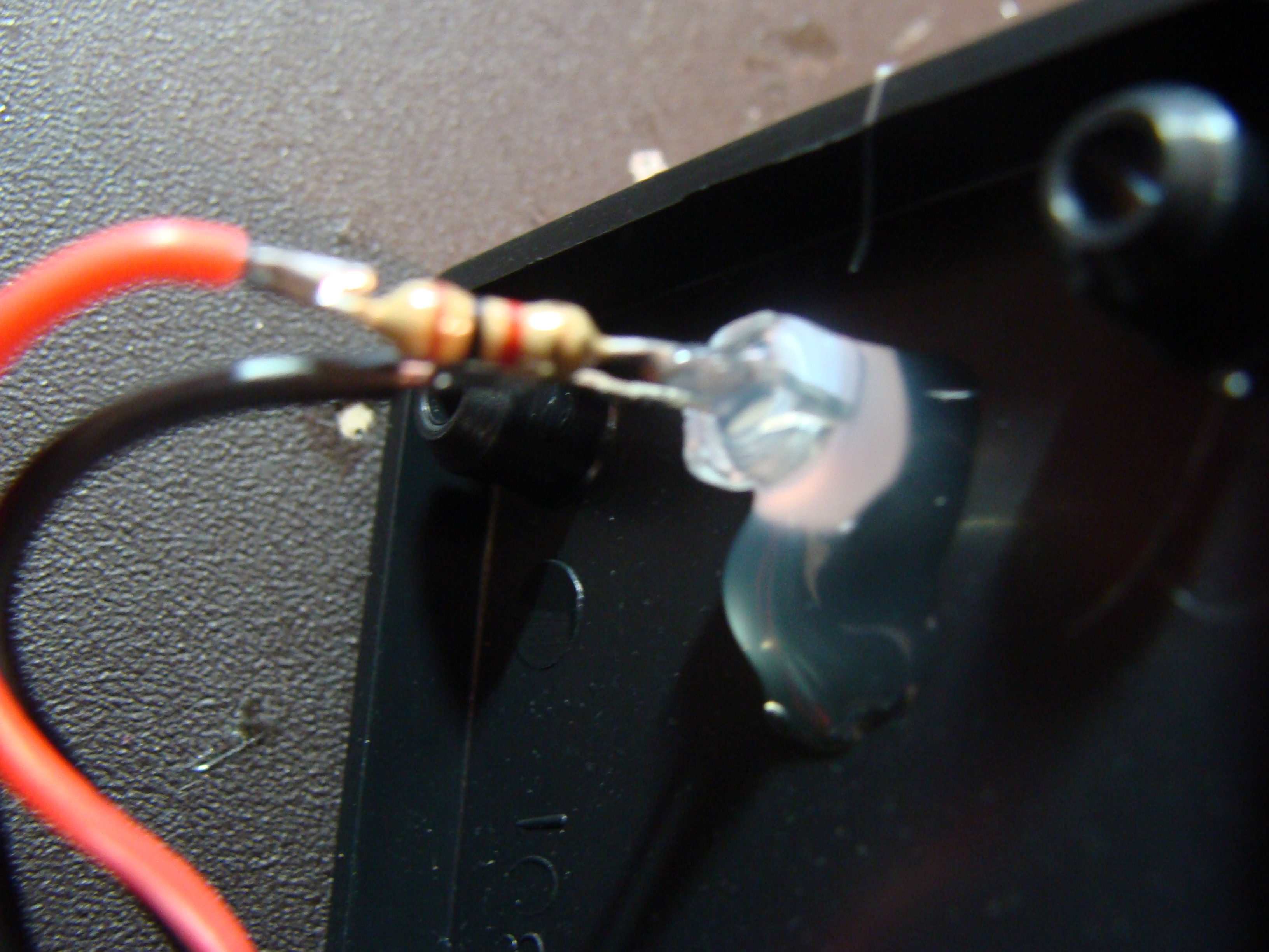
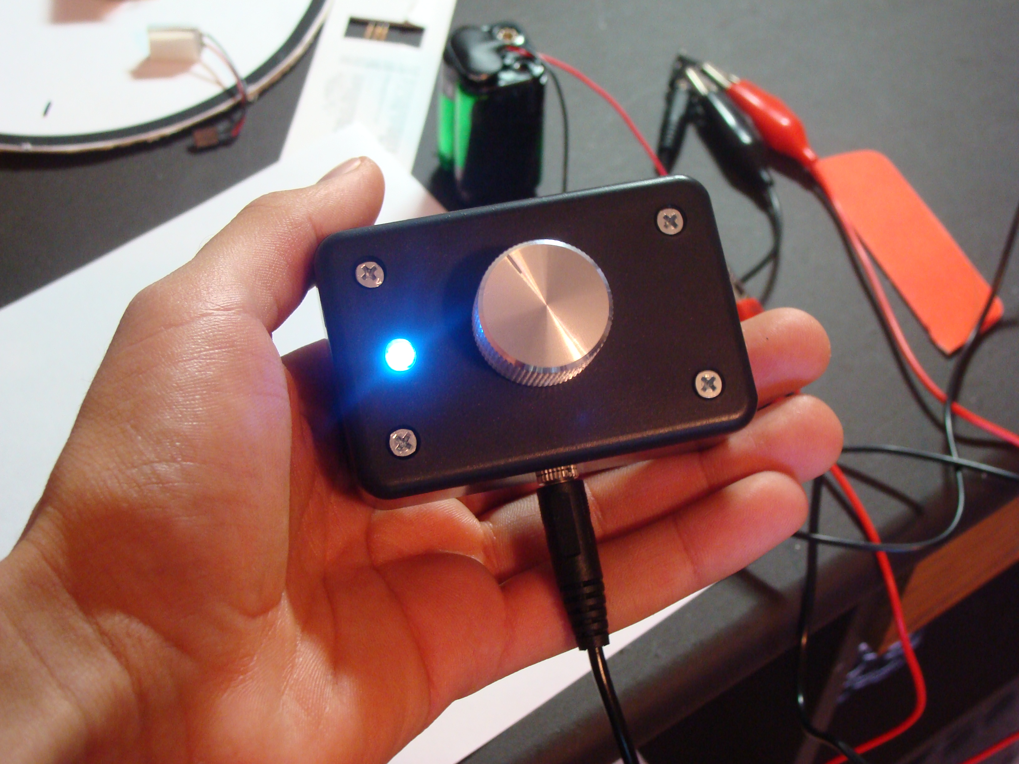
Then the LED is connected to a 1k resistor to limit the current and then the LED is wired to power. A bit of hot glue holds it in place.
The potentiometer is then glued in place on the bottom of the box, right below the hole drilled in the top.

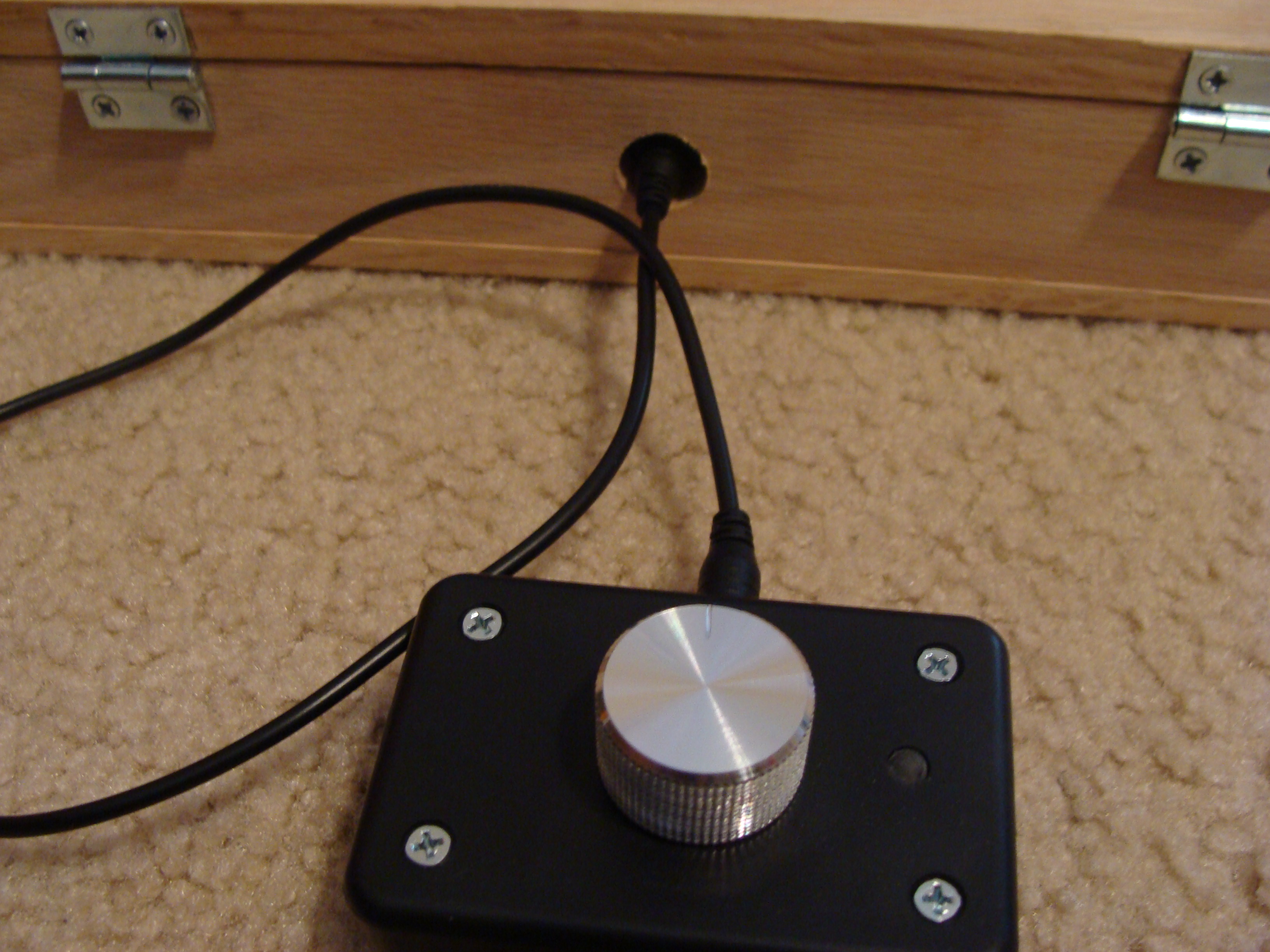
Finally the top is screwed on and the knob is glued on.
A quick power check is done to see if the LED properly lights up
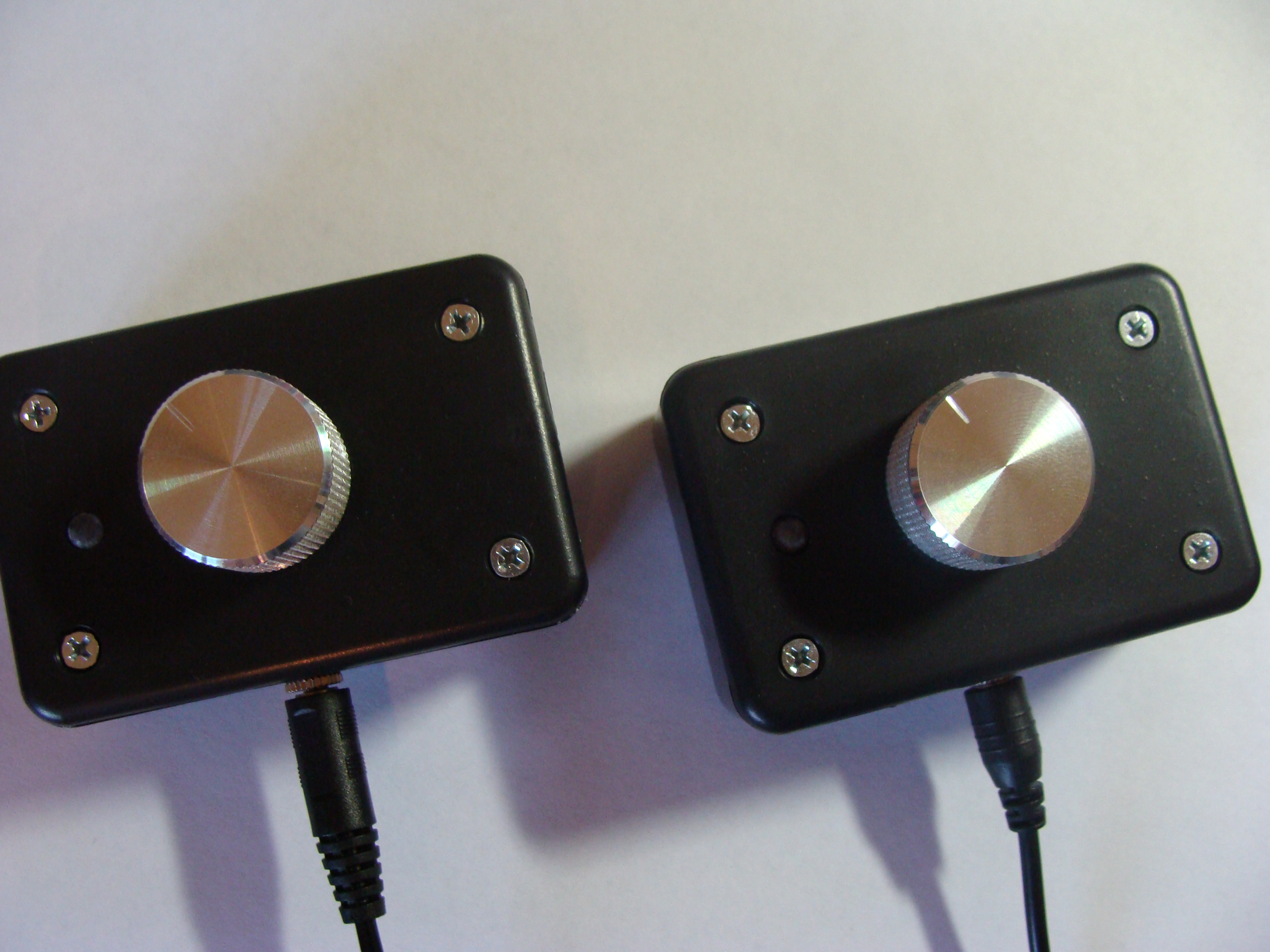
A second one is constructed the same way, and so there you have 2 pong paddles.
Constructing The Case
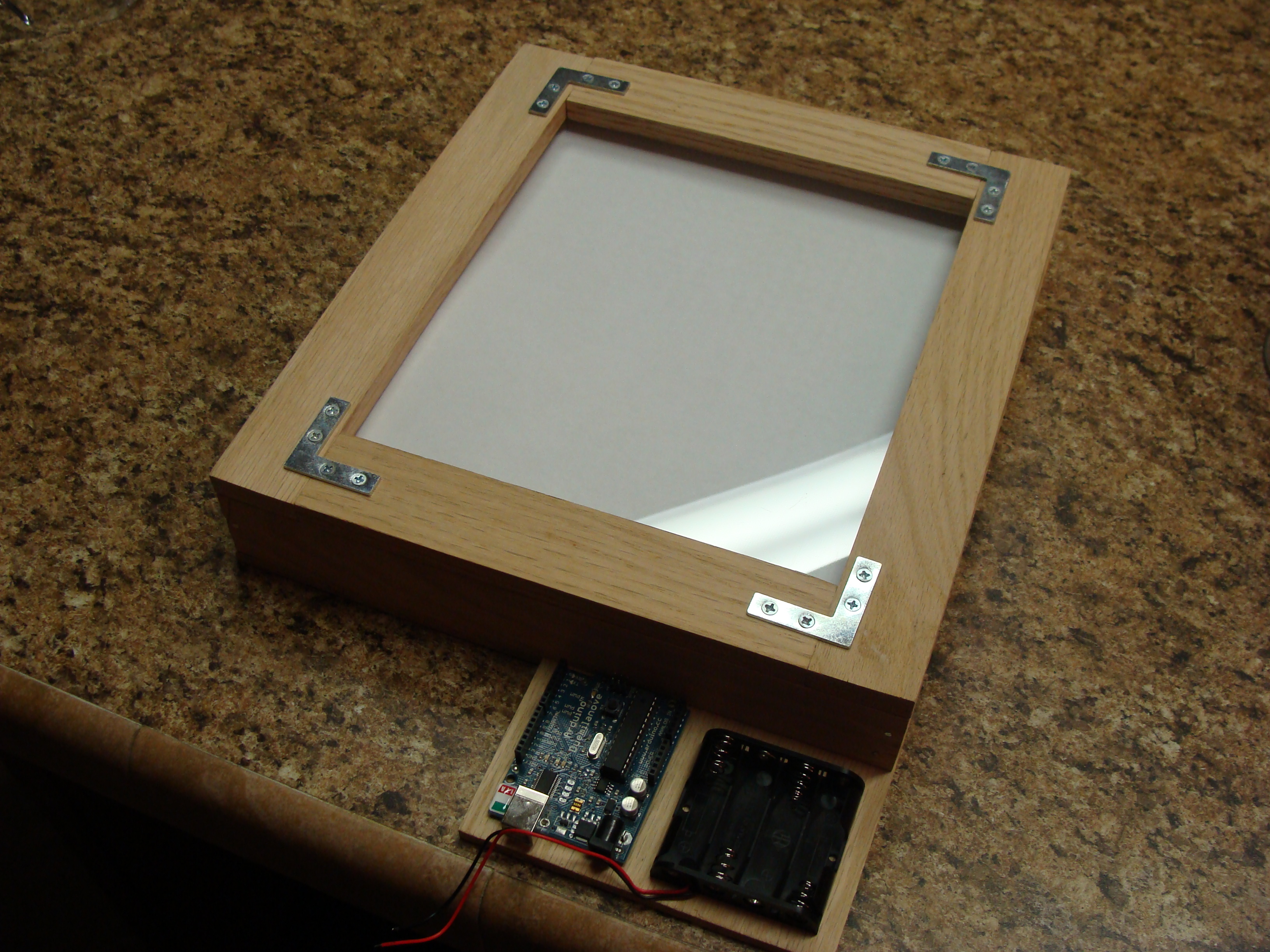
The Case is built from hardwood bought at a local hardware store. The case is a bit big for the screen, but there has to be room for the circuit boards to fit inside.
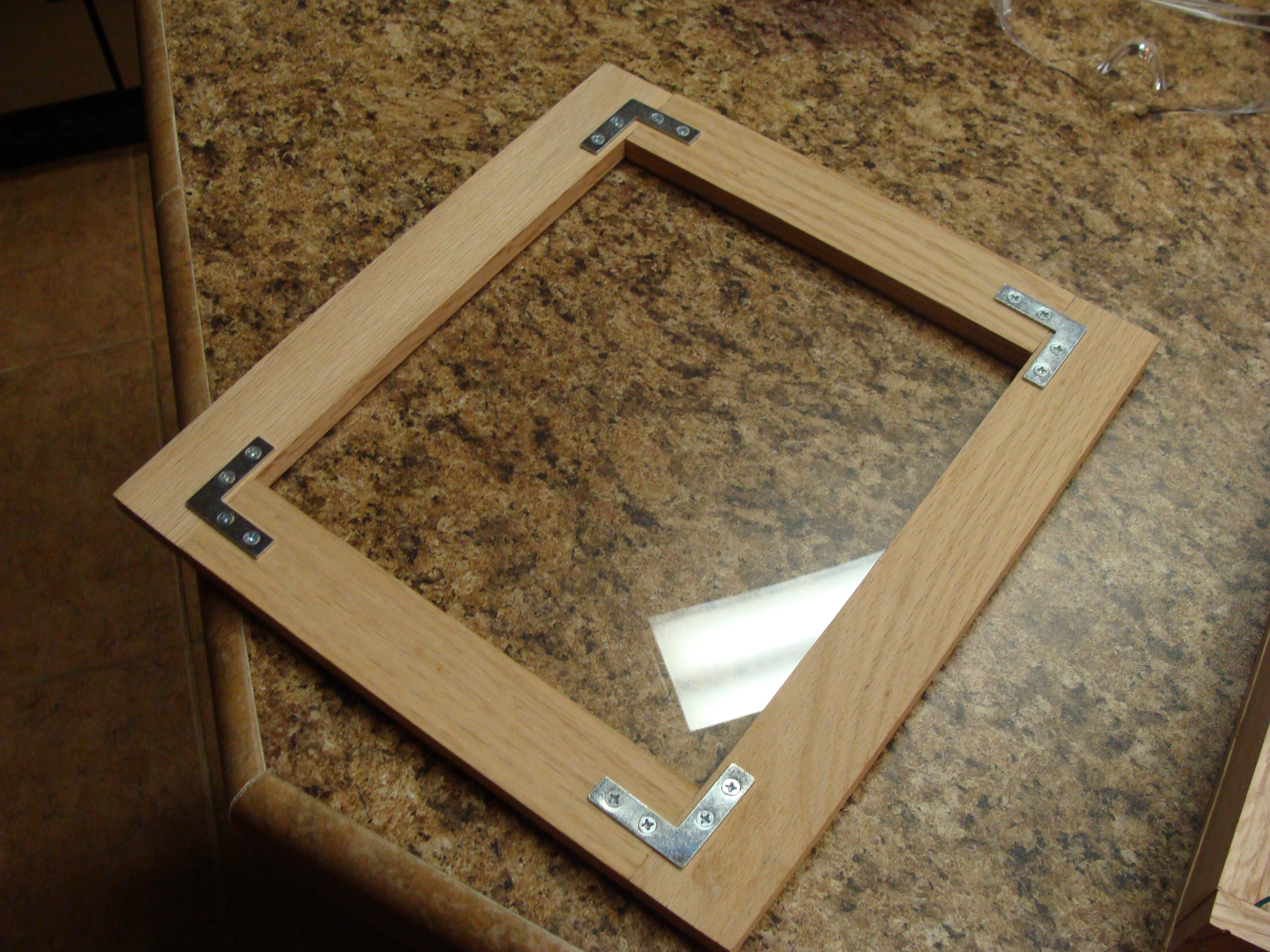
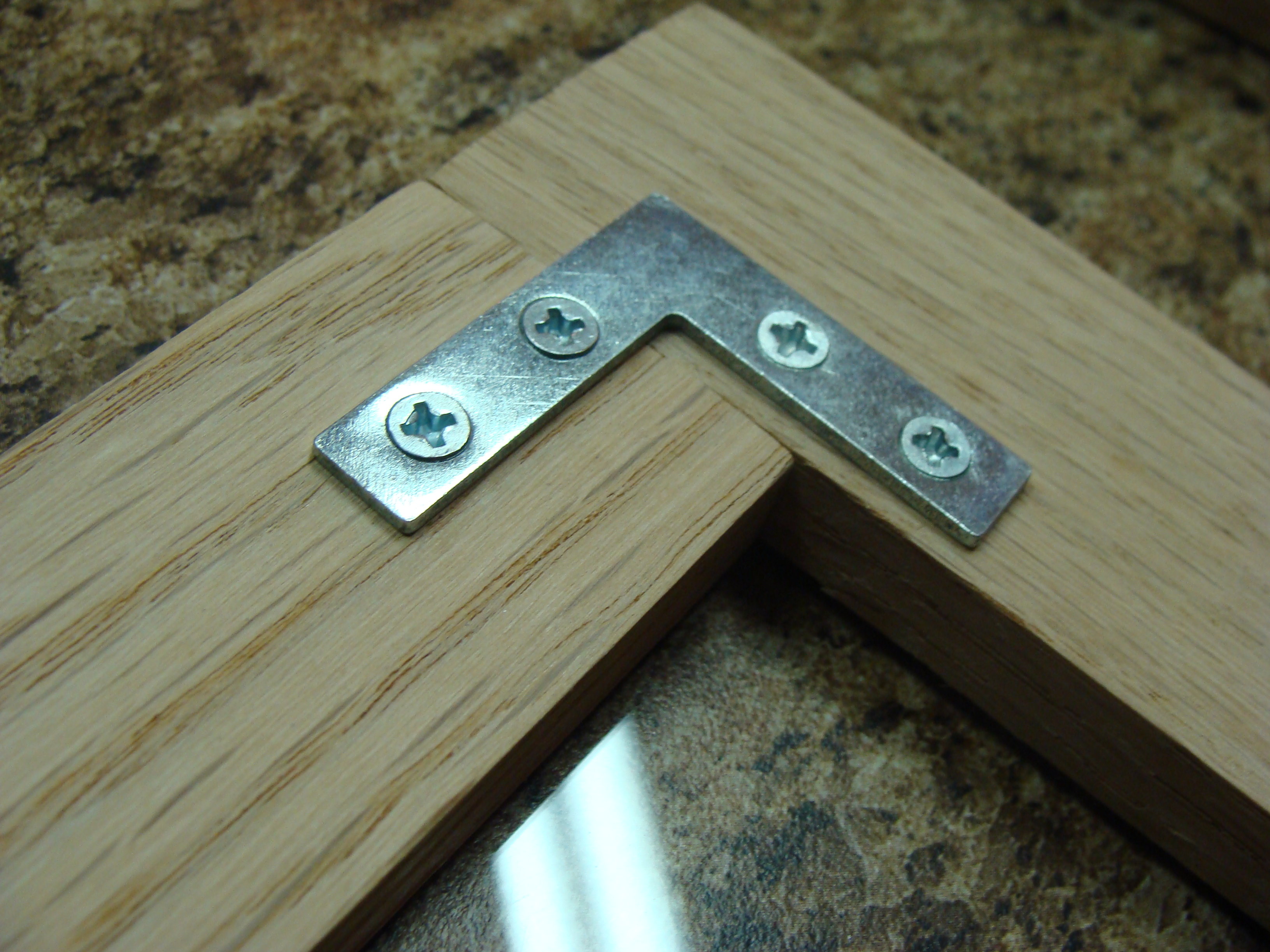
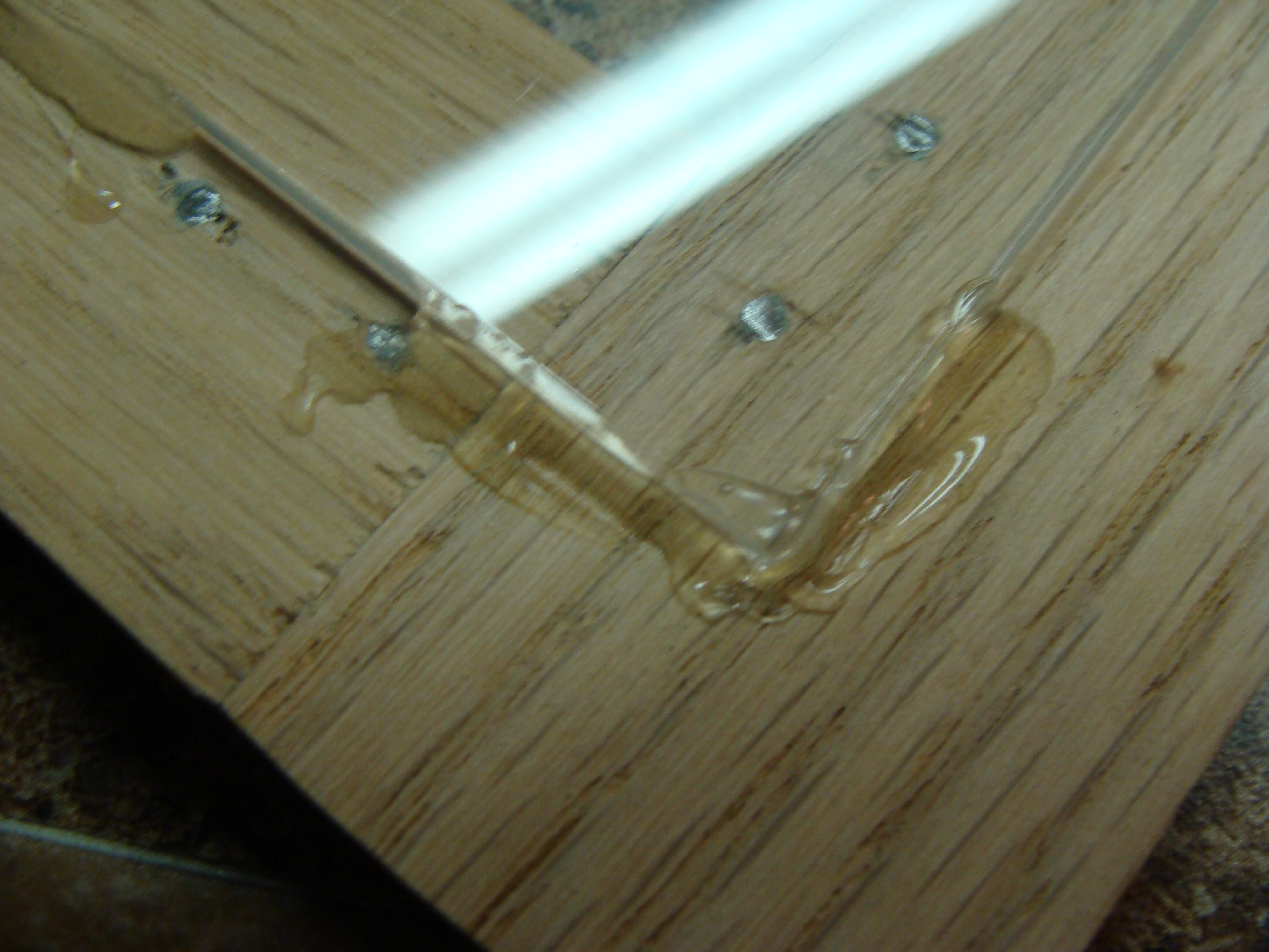
The case’s door is also made from hardwood. A piece of Lexan acts as the window for the case allowing the players to see the screen within. The wood on the door is held together with angle brackets. The Lexan window is hot glued on the back.
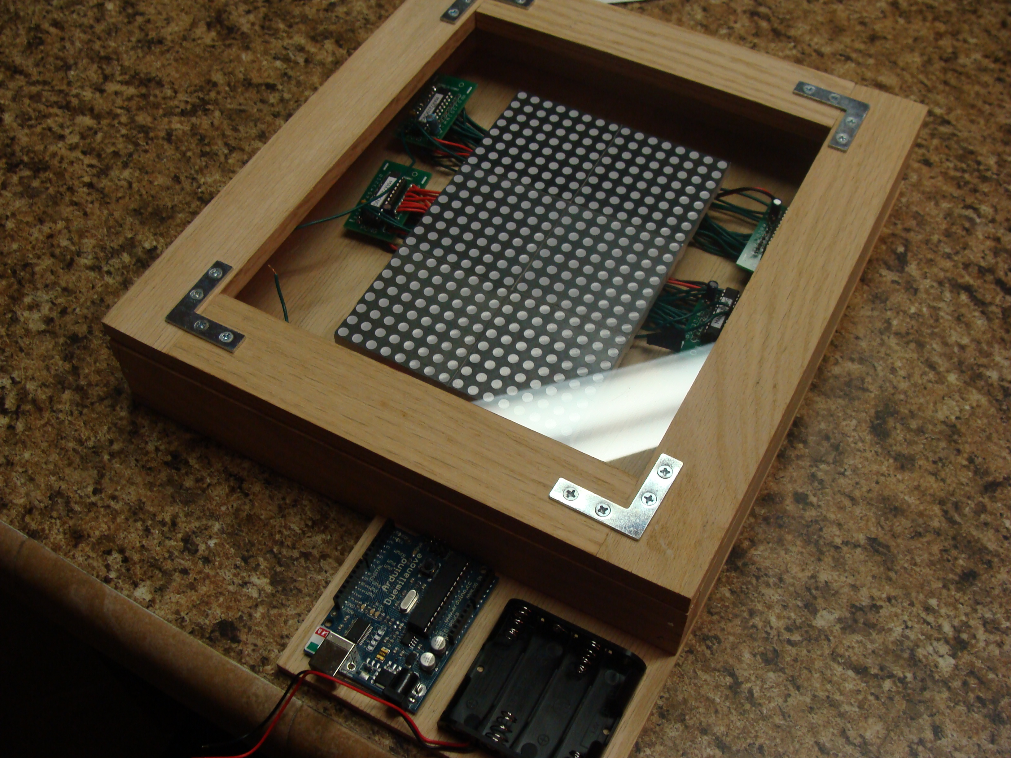
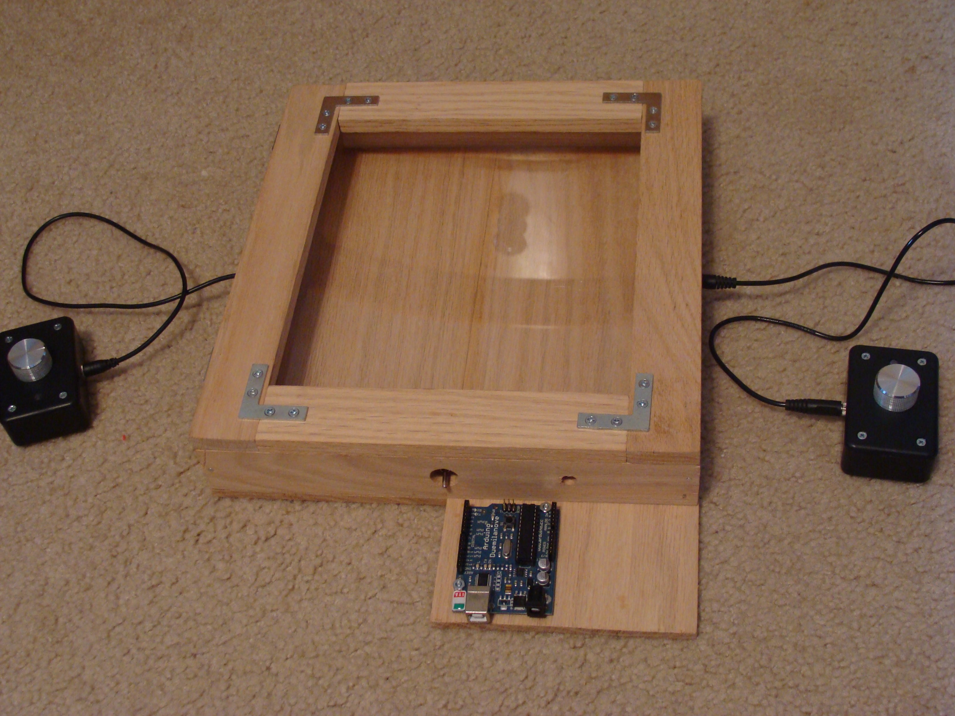
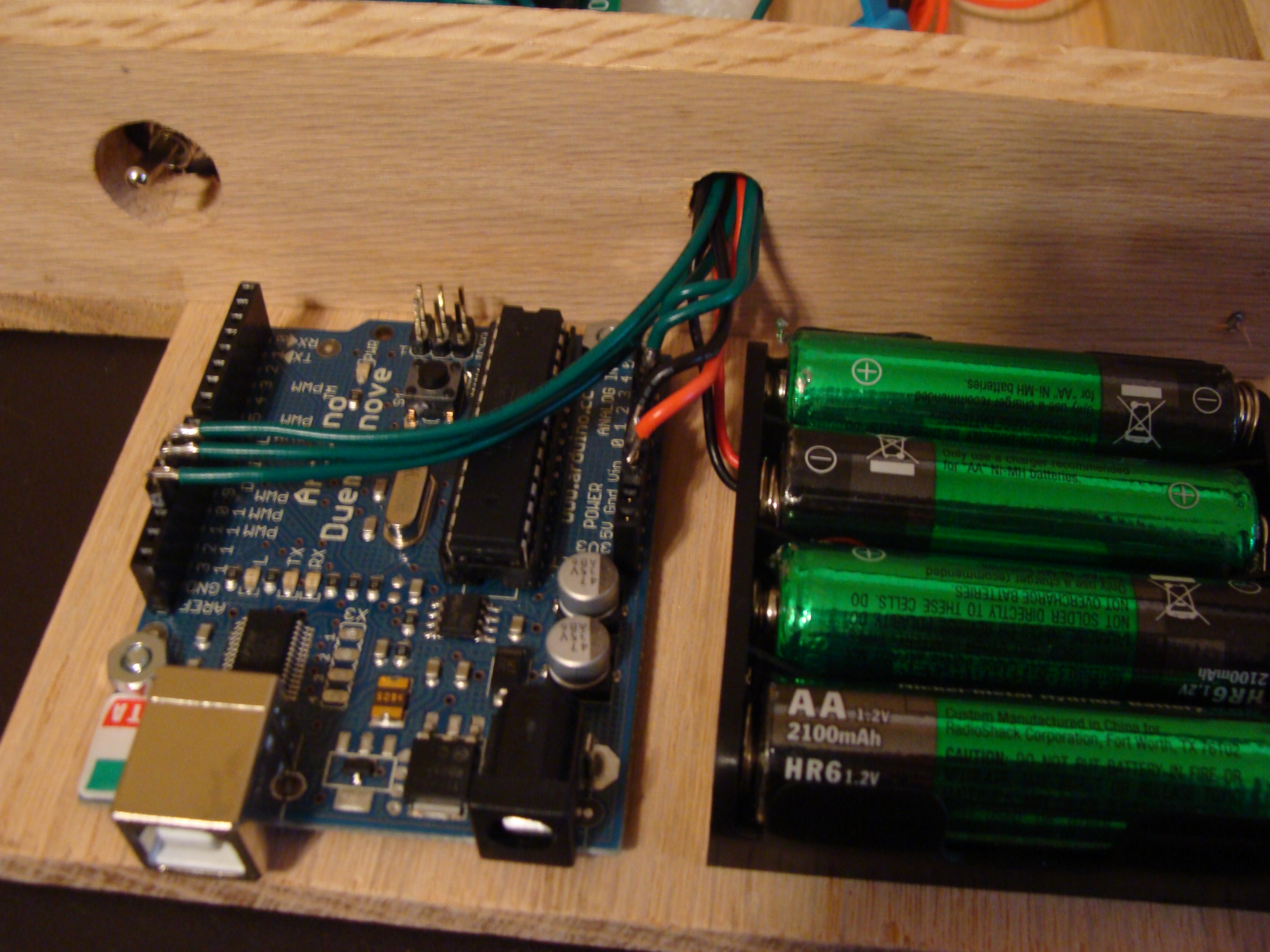
You can see the case coming together with the door temporarily set on. Also the case is designed to have a platform on the side for the Arduino and battery pack to sit. This makes both easily accessible so batteries can be changed and the Arduino can be programmed. A piece of paper is placed in to act as a diffuser. This may or may not stay part of the design.
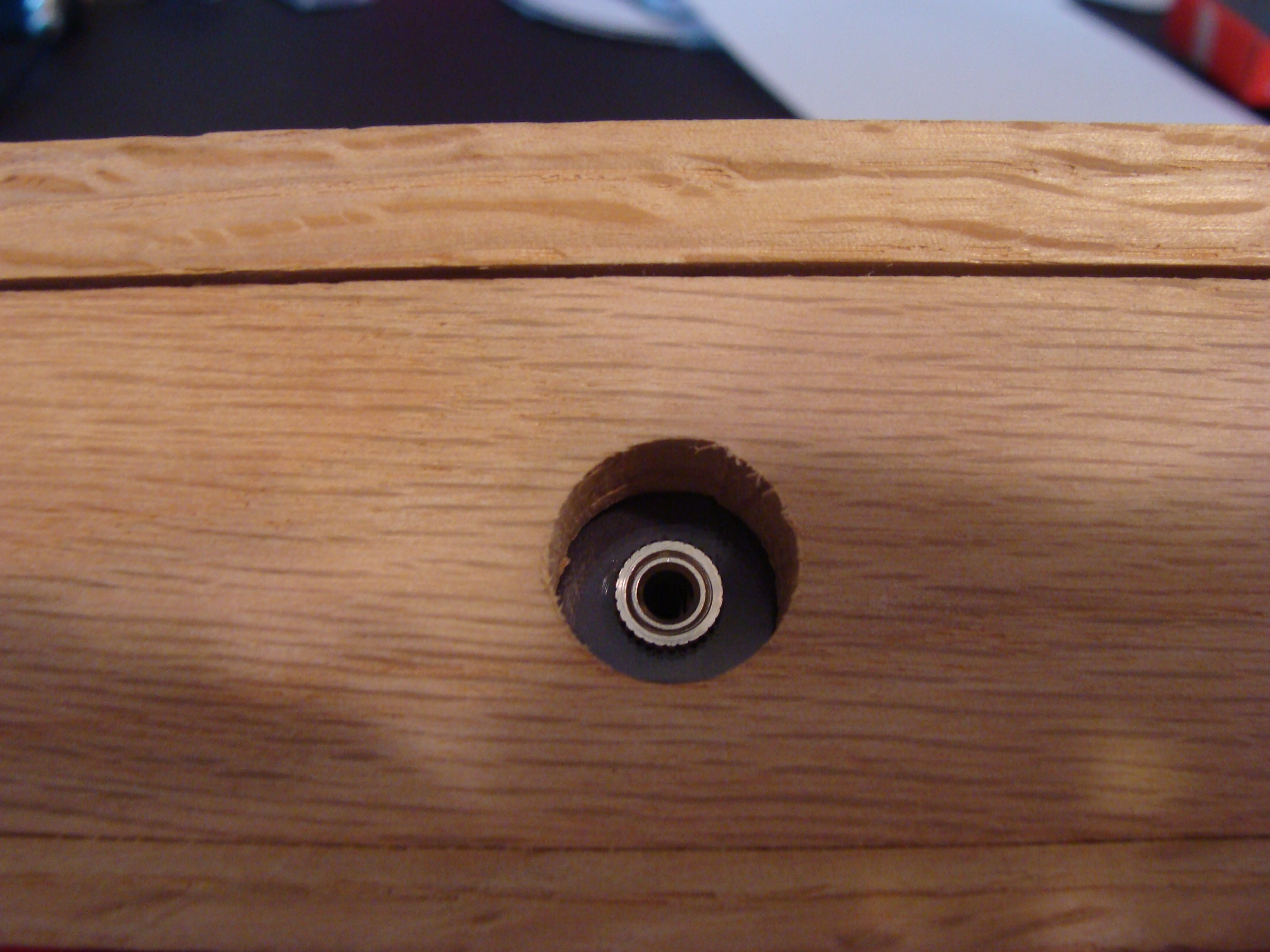
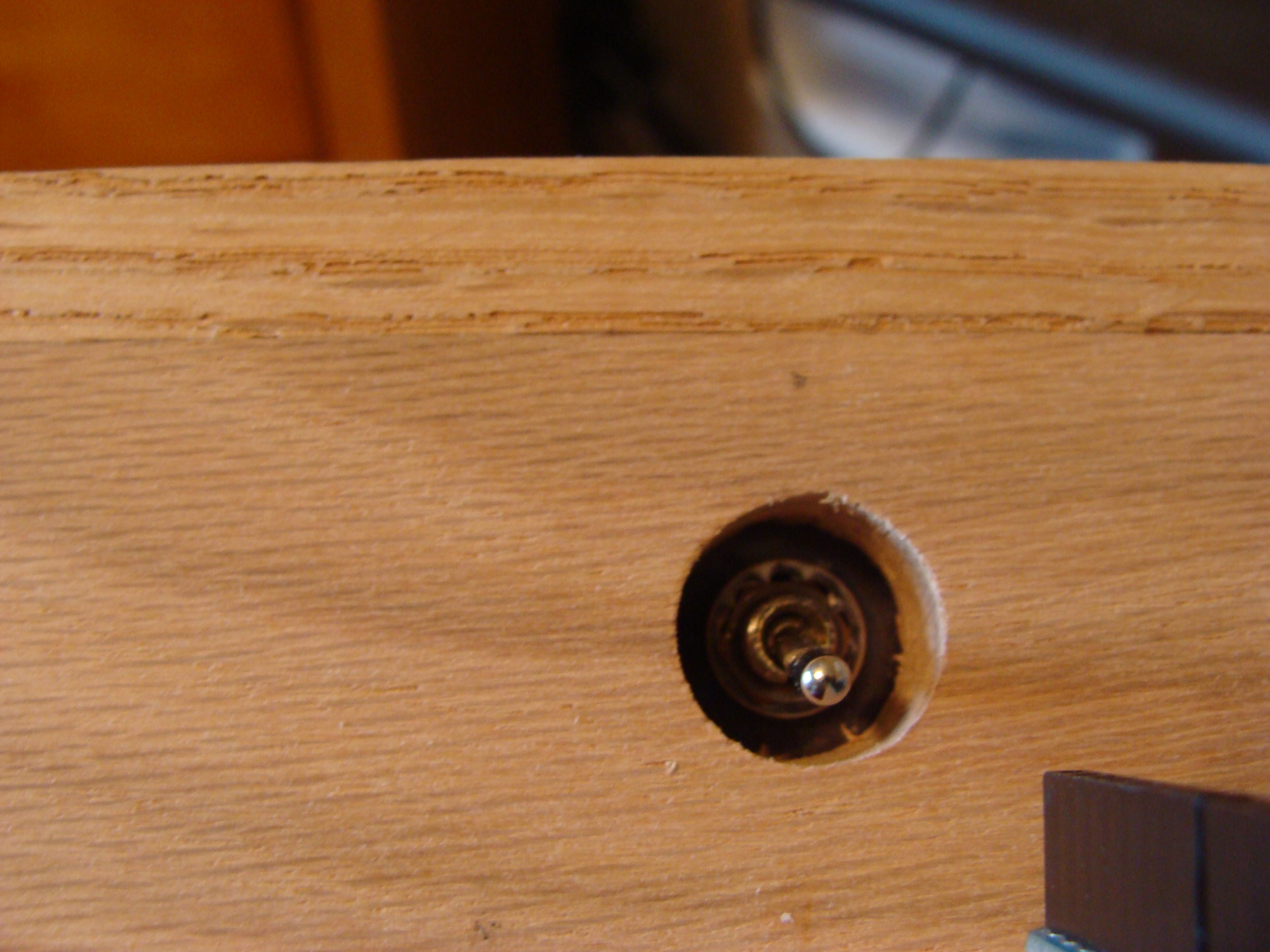
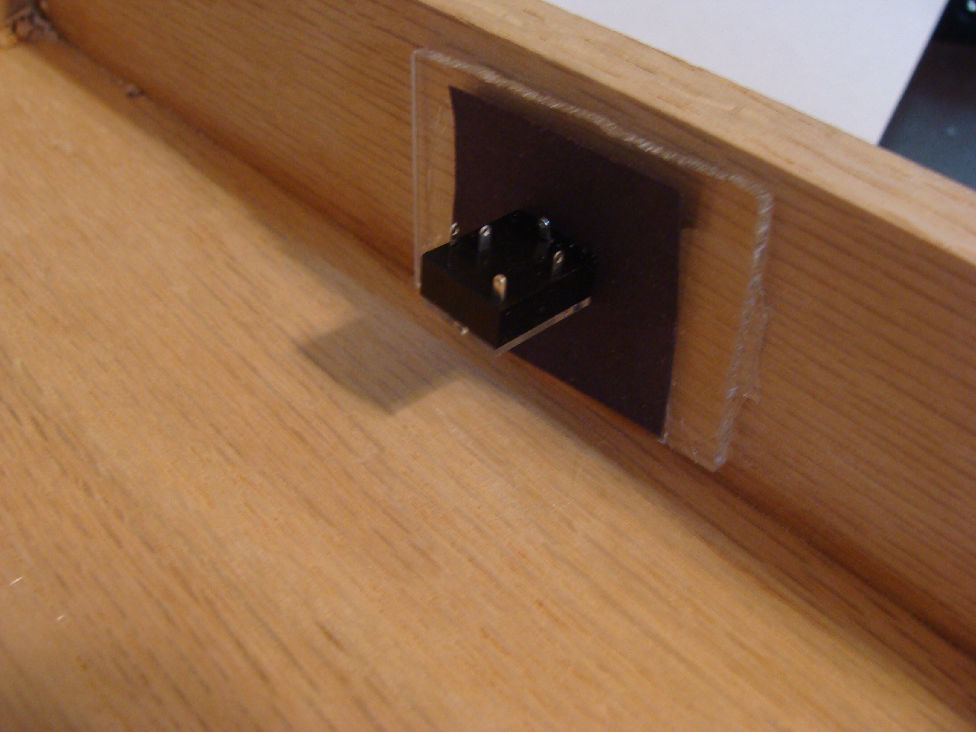
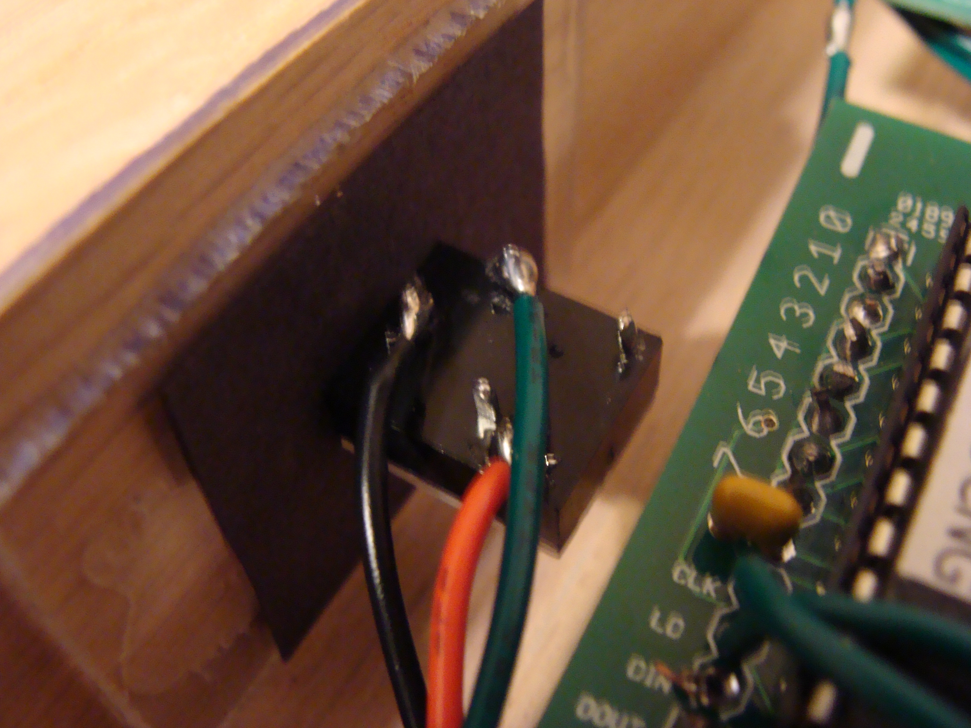
Holes are drilled in the side of the case for the audio jack plugs and for the power switch. The wood of the case is too thick to bolt on the switch or plugs, so instead the switch and plugs are bolted on a piece of Lexan which is glued behind the hole. A piece of black paper adds a bit of aesthetics to the Lexan mount.
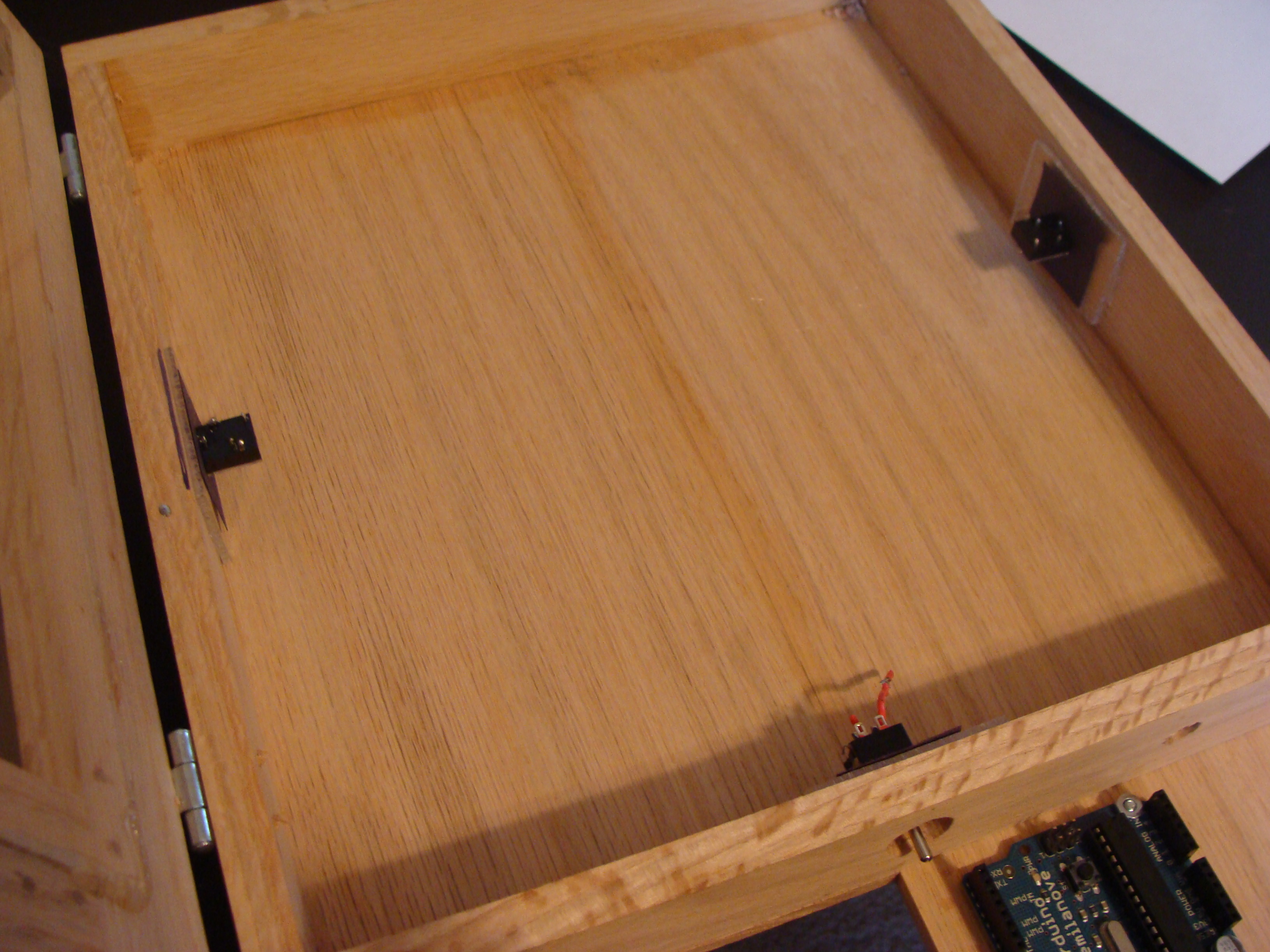
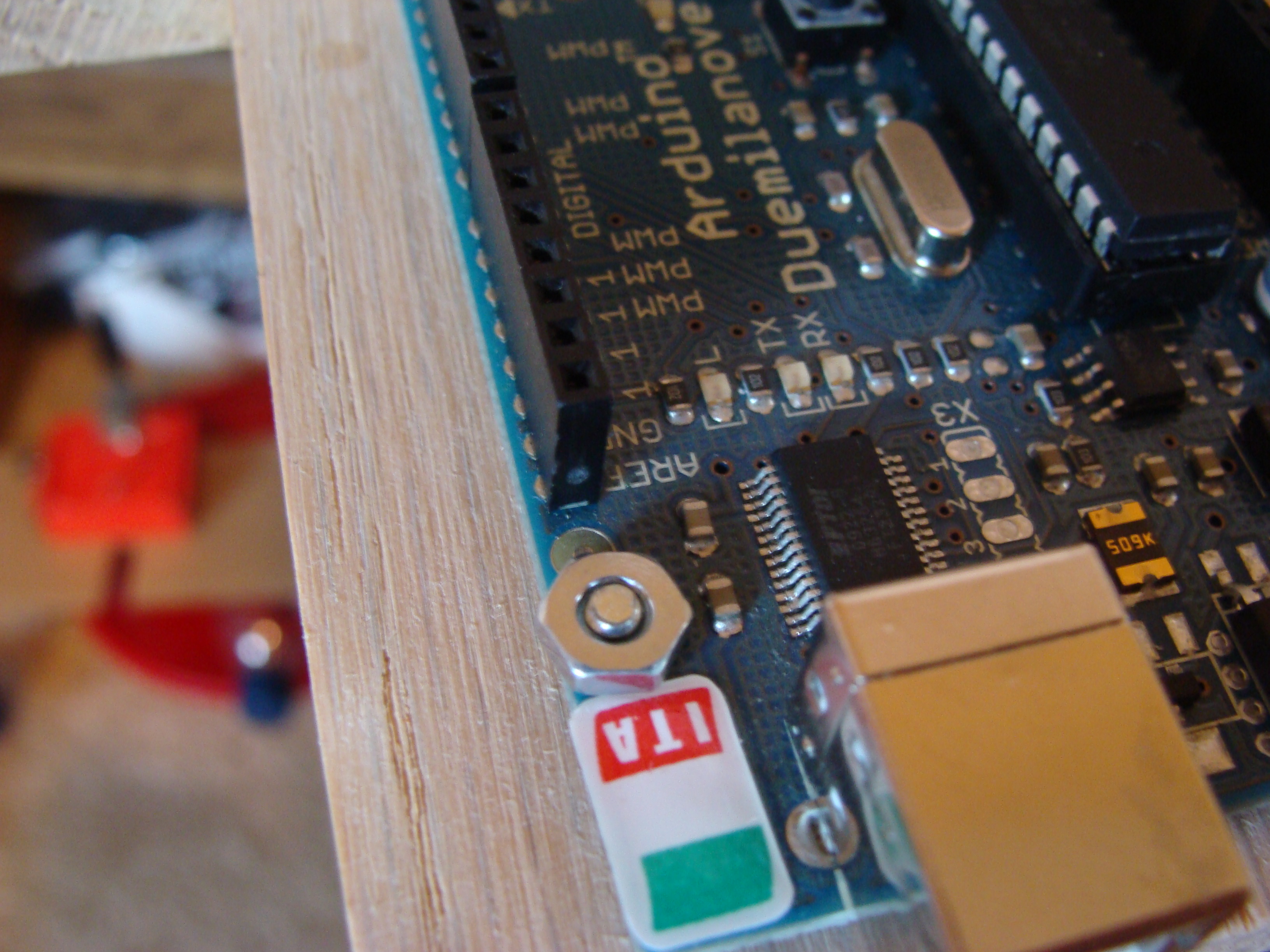
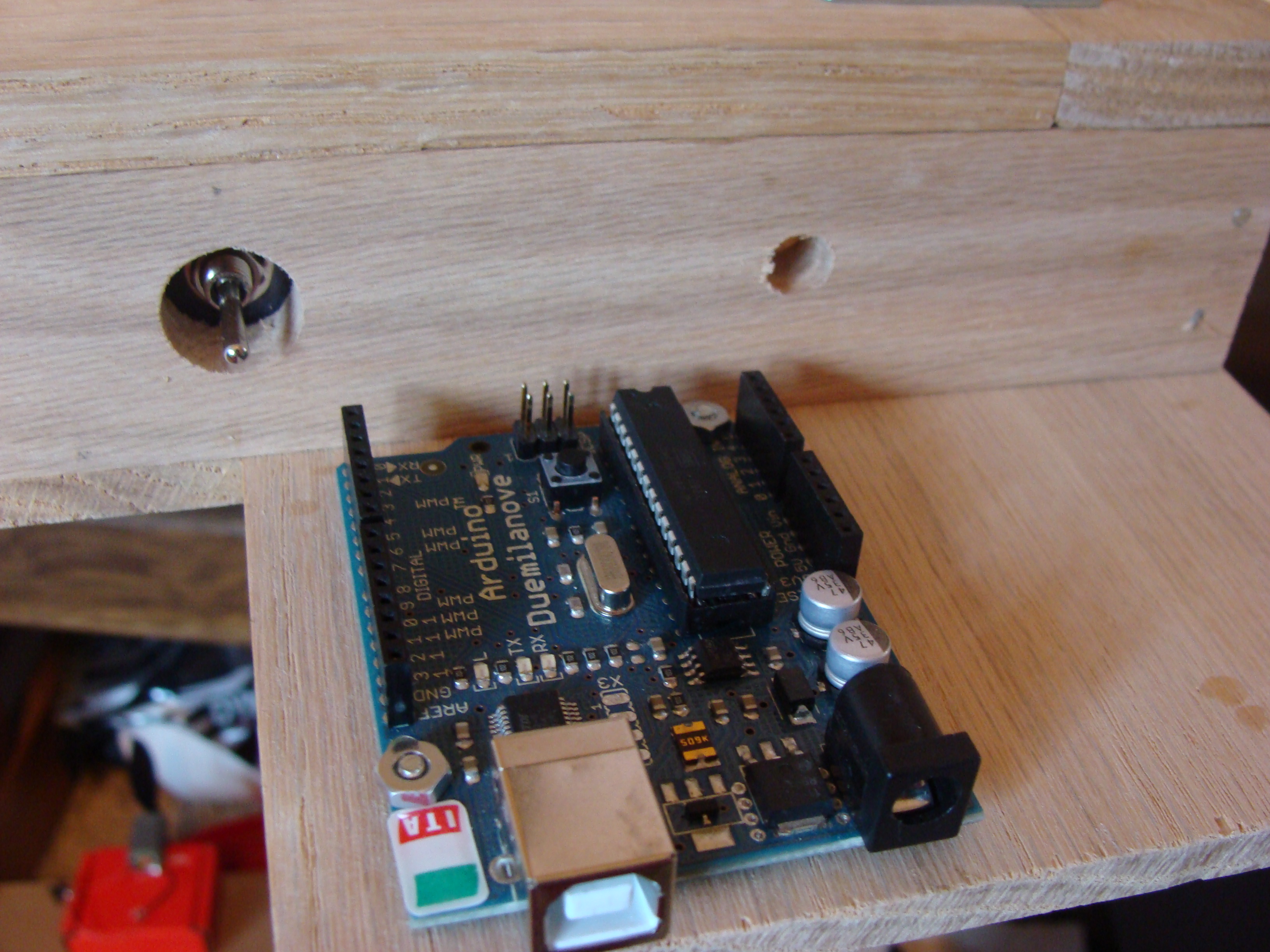
2 holes are drilled into the platform to bolt the Arduino Duemilanove down. The battery pack will be glued down next to it later.
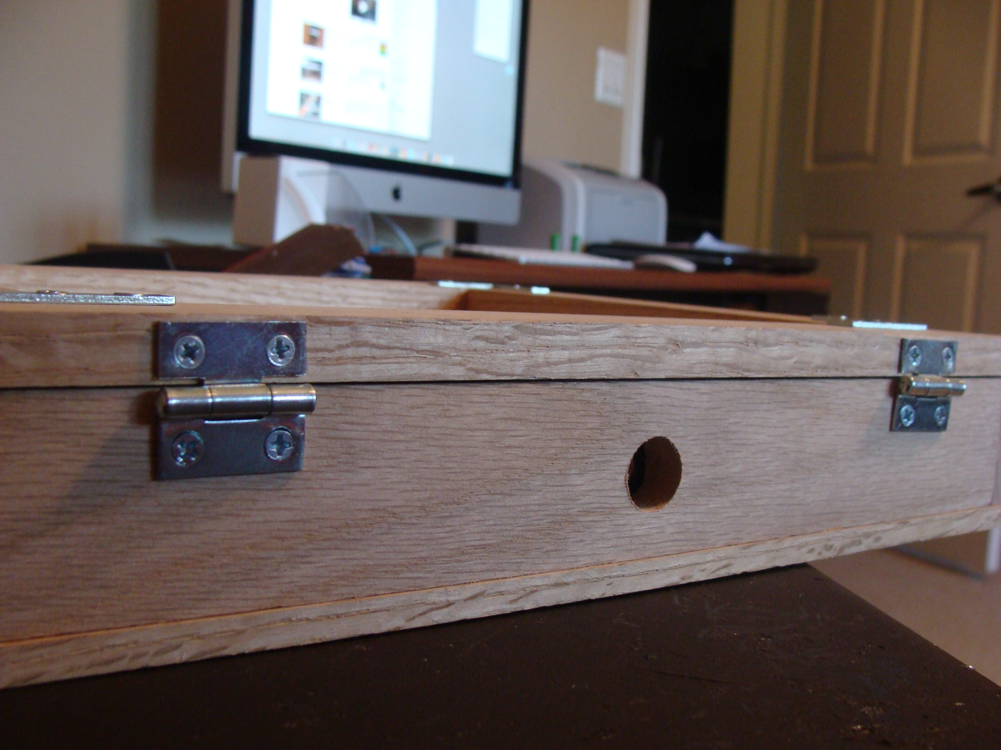
The door finally is attached with hinges so the inside screen and electronics can easily be accessed if need be it or to show to anyone who is interested in the “guts” of the project.

You can see below how the paddles plug into the case like I have been talking about all along.
Now it is time to start wiring up the audio jacks, distributing power, and plugging everything into the Arduino micro-controller.
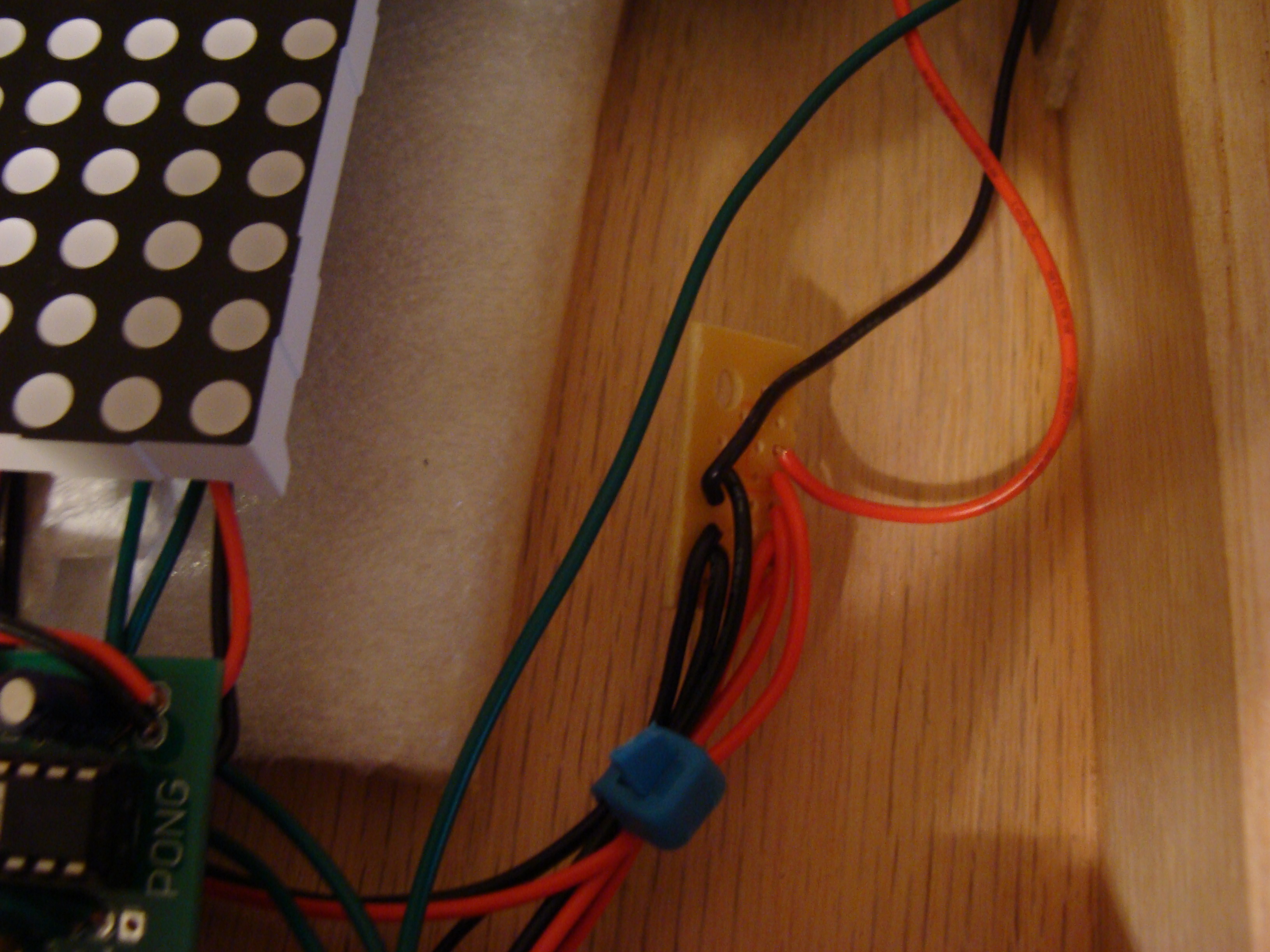
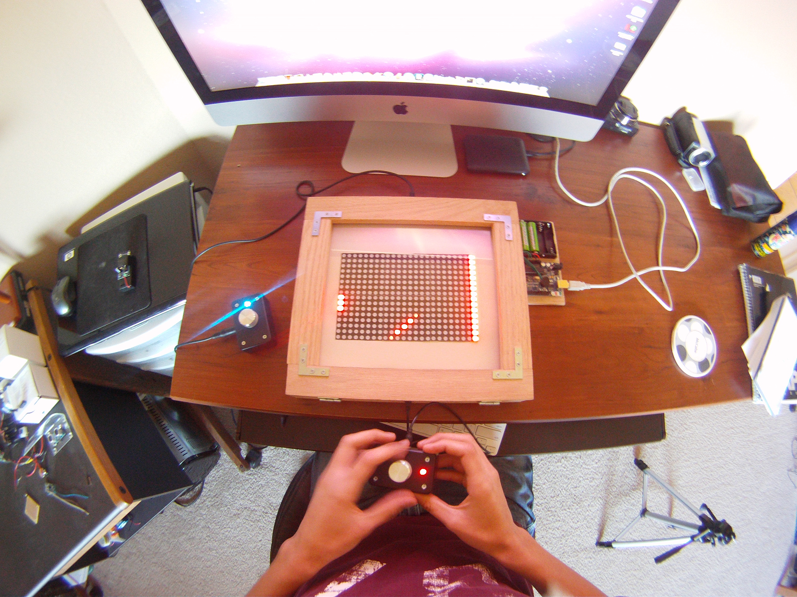
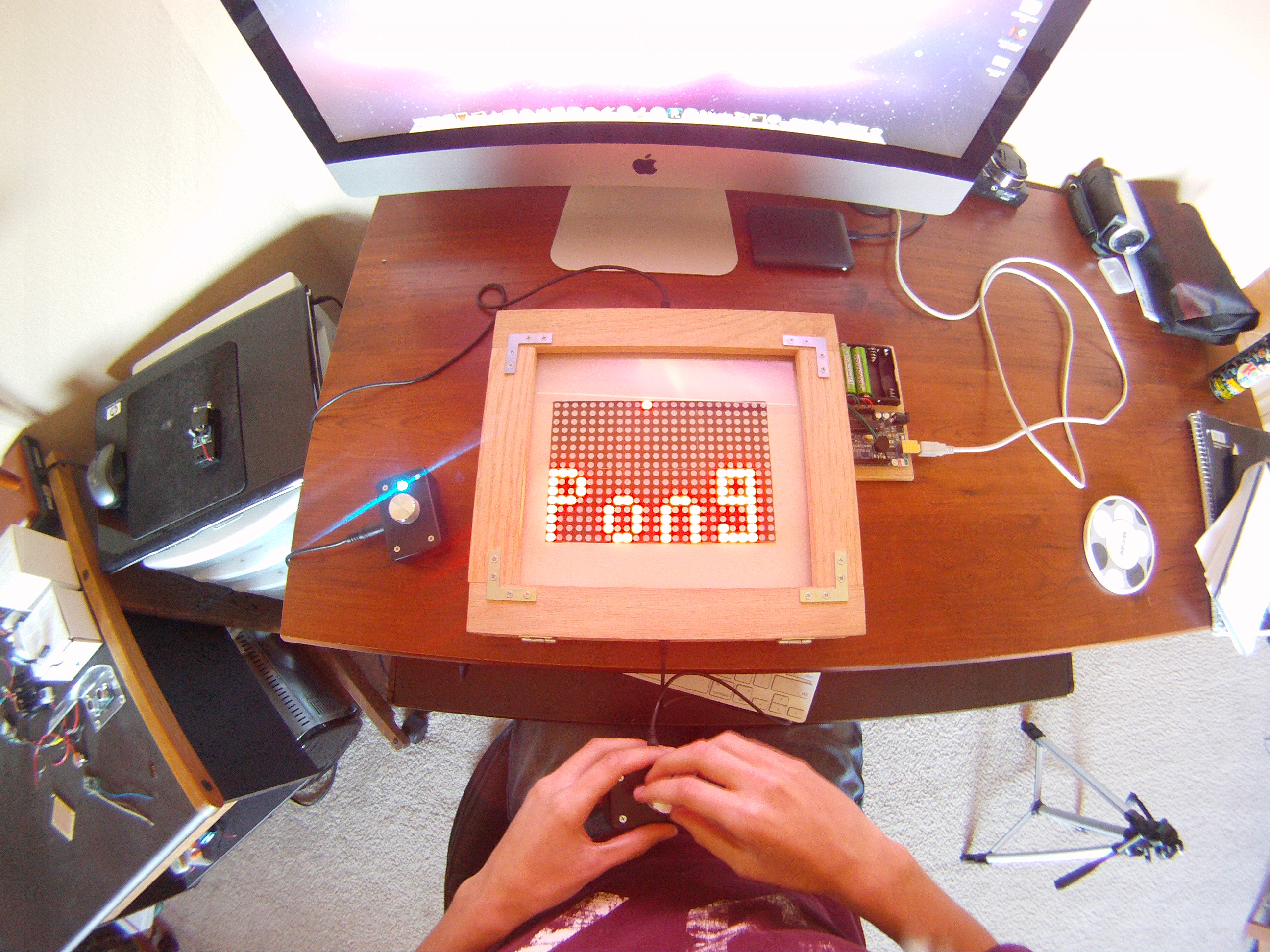
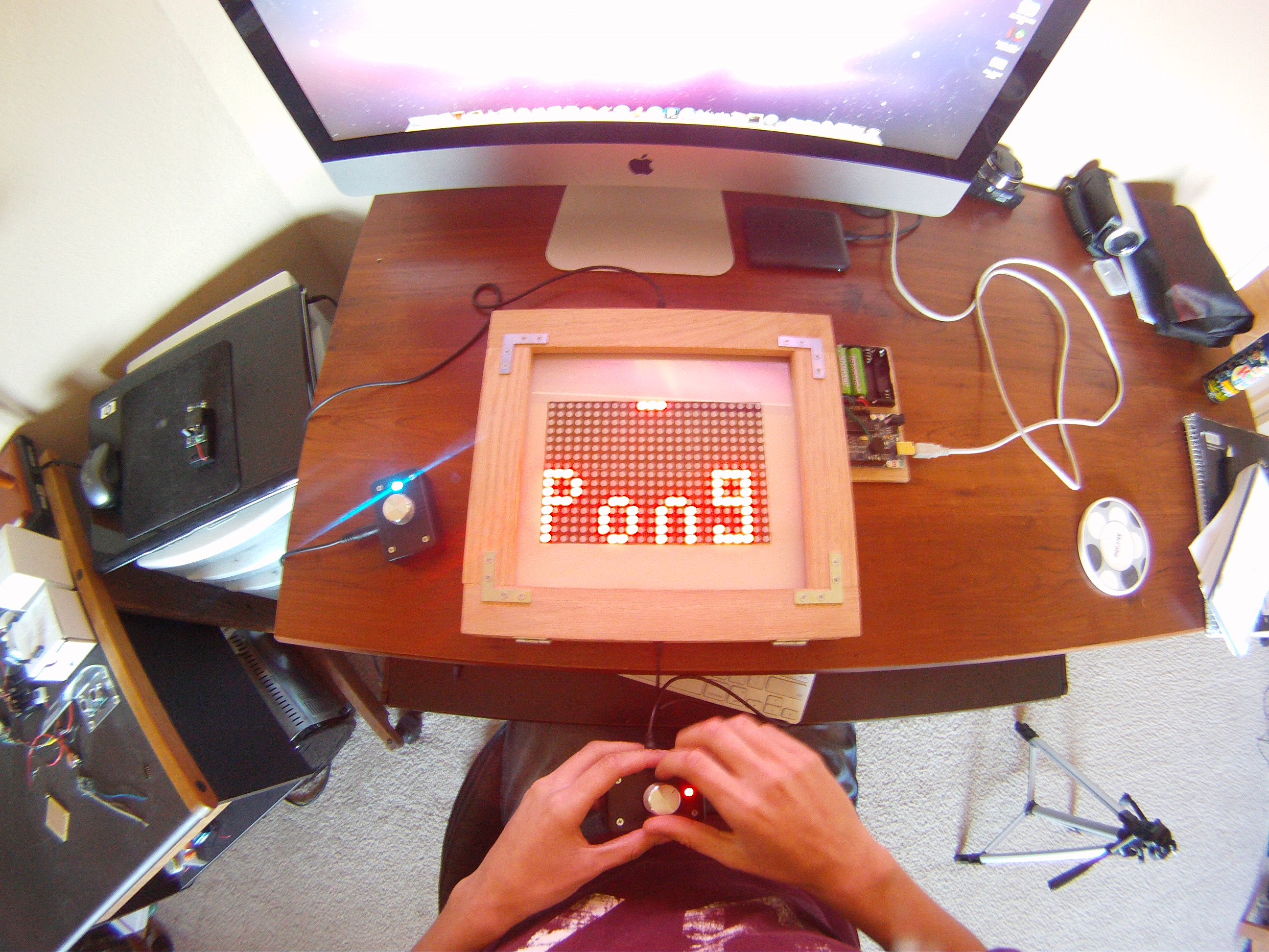
Here is the completed game - all wired up and ready to program.
Modes and Features
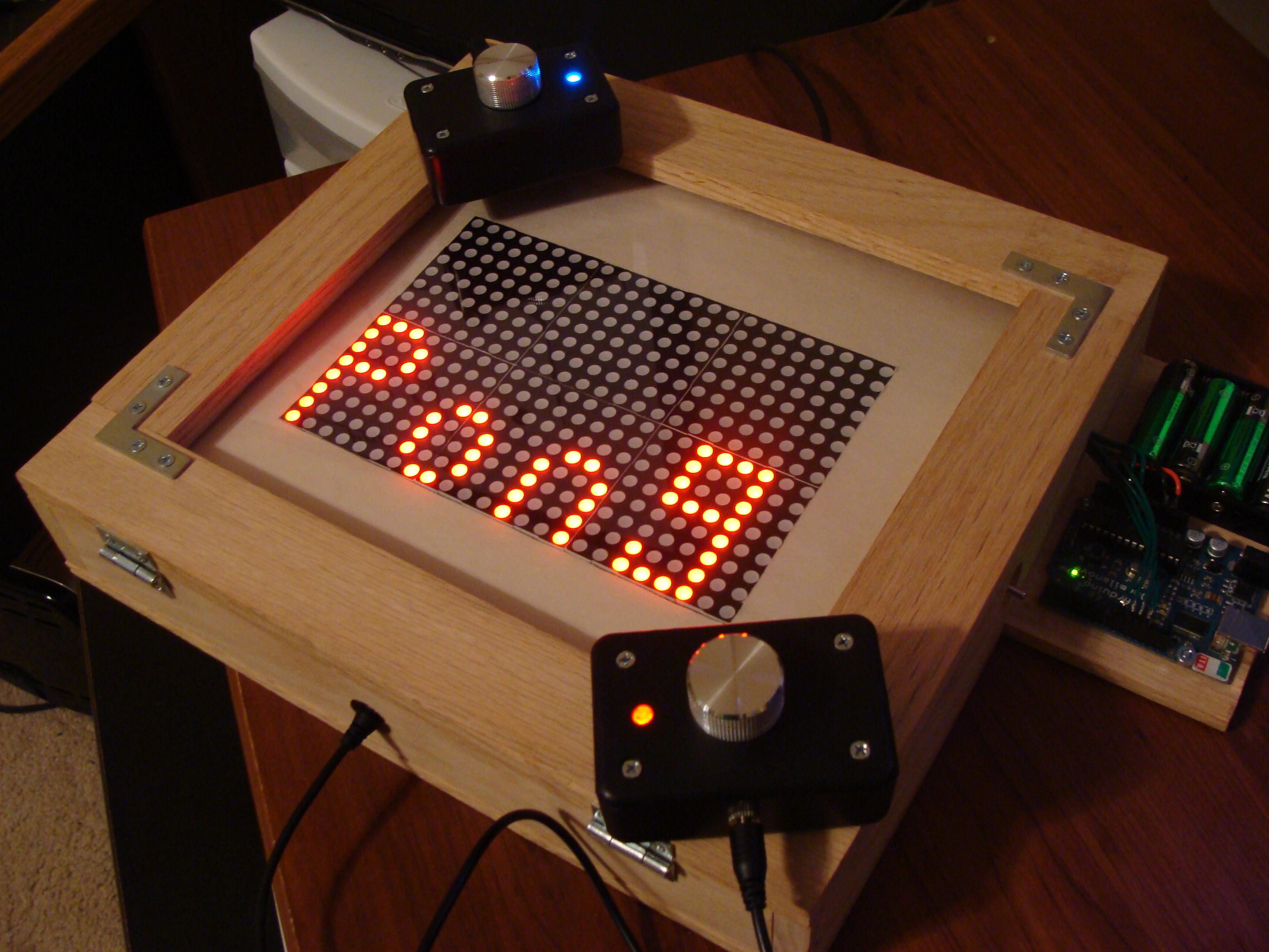
The first function is score keeping. It keeps score and displays the score after each point. The first player to get five points wins. Once five points are scored, the score will flash for a few seconds indicating there is a winner and the code will then start a new round.

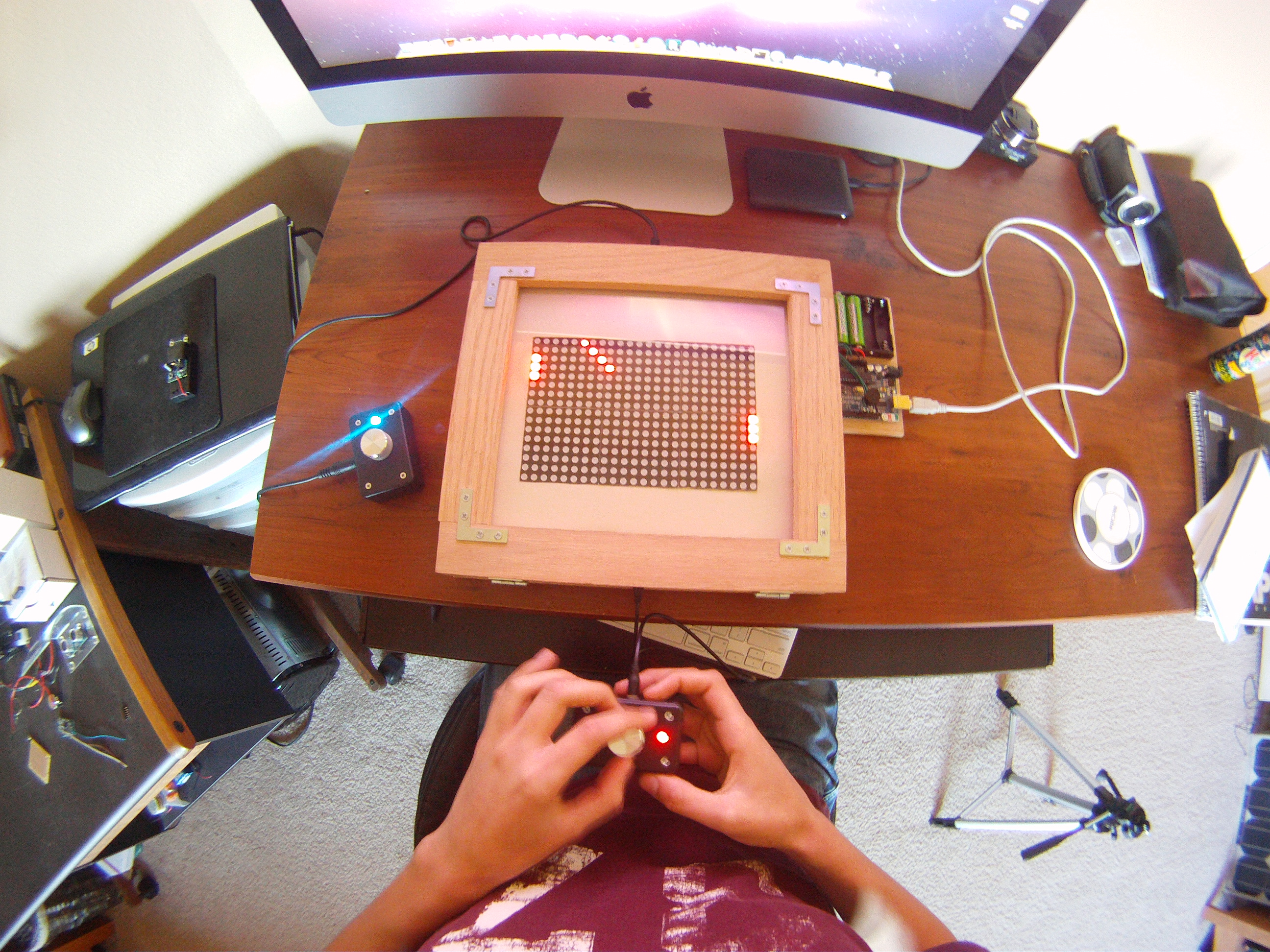
There are three modes. Each of the modes are selectable for the first three seconds after a restart of the game. The user can pick which mode to play by spinning their knob to choose the mode. The mode is displayed during those first three seconds at the top of the screen. Each mode is indicated by either 1, 2, or 3 LEDs that corresponds to the mode chosen by the user.
Notice the lights at the top of the screen indicating the mode currently selected:
The first mode is a 2 player pong game with the paddles set to 3 pixels wide.
The second mode is also 2 player pong, but the paddles are 2 pixels wide instead of 3. This makes the game more challenging to play.
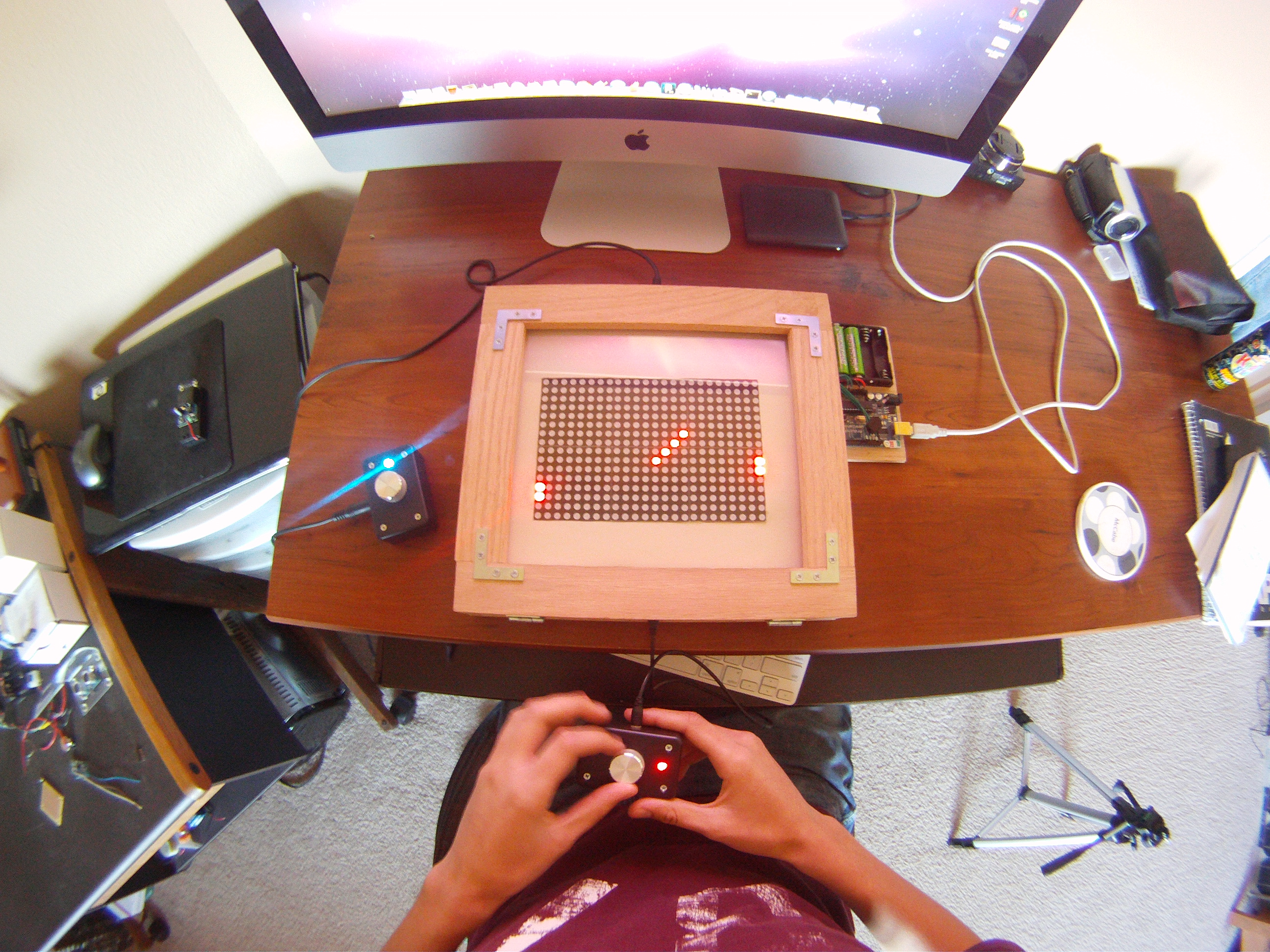
The third mode is a one player game where the user can practice their skill by playing against a “wall”.