Refloaster Oven
Intro
As I make more electronic gizmos, I try to grow in efficiency. This includes using more SMD (surface mount device) components in my circuit designs. SMD parts are not impossible to solder by hand, but they can be tricky. This “Refloaster Oven” is one tool that will make my SMD assembly easier. This oven will allow me to automate my reflow soldering. I will also try to laser cut some SMD solder stencils to make applying the solder paste easier as well.
In the end I am hoping the steps for me to assemble a SMD circuit board I design will look like this:
- Design the PCB in EagleCAD and have them fabricated
- While waiting for the PCBs to arrive, laser cut the solder stencil
- Apply solder paste to the PCB using the solder stencil
- Place the SMD parts onto the PCB using tweezers
- Put the board in the Refloaster Oven to reflow solder the board
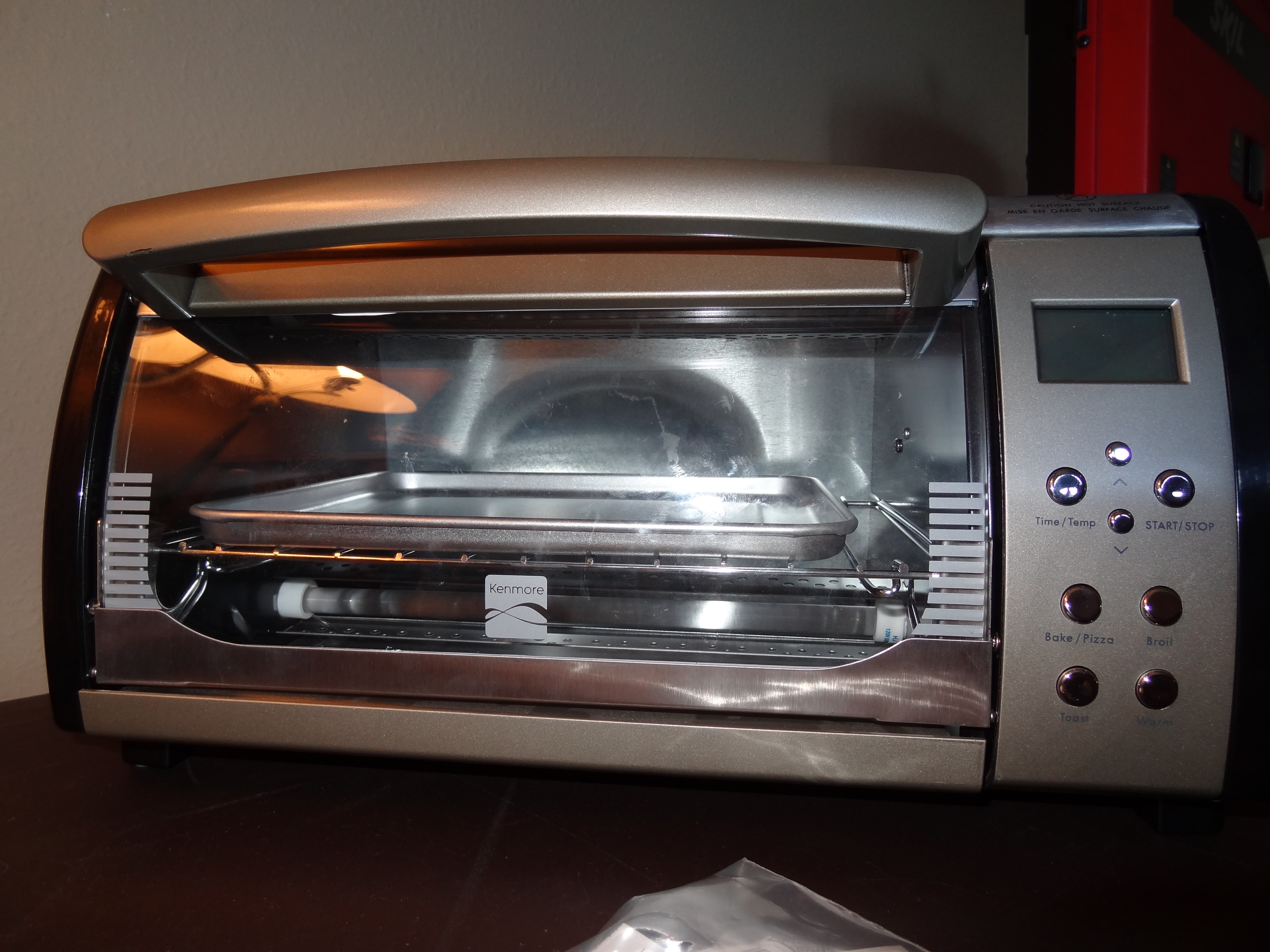
Toaster Hacking
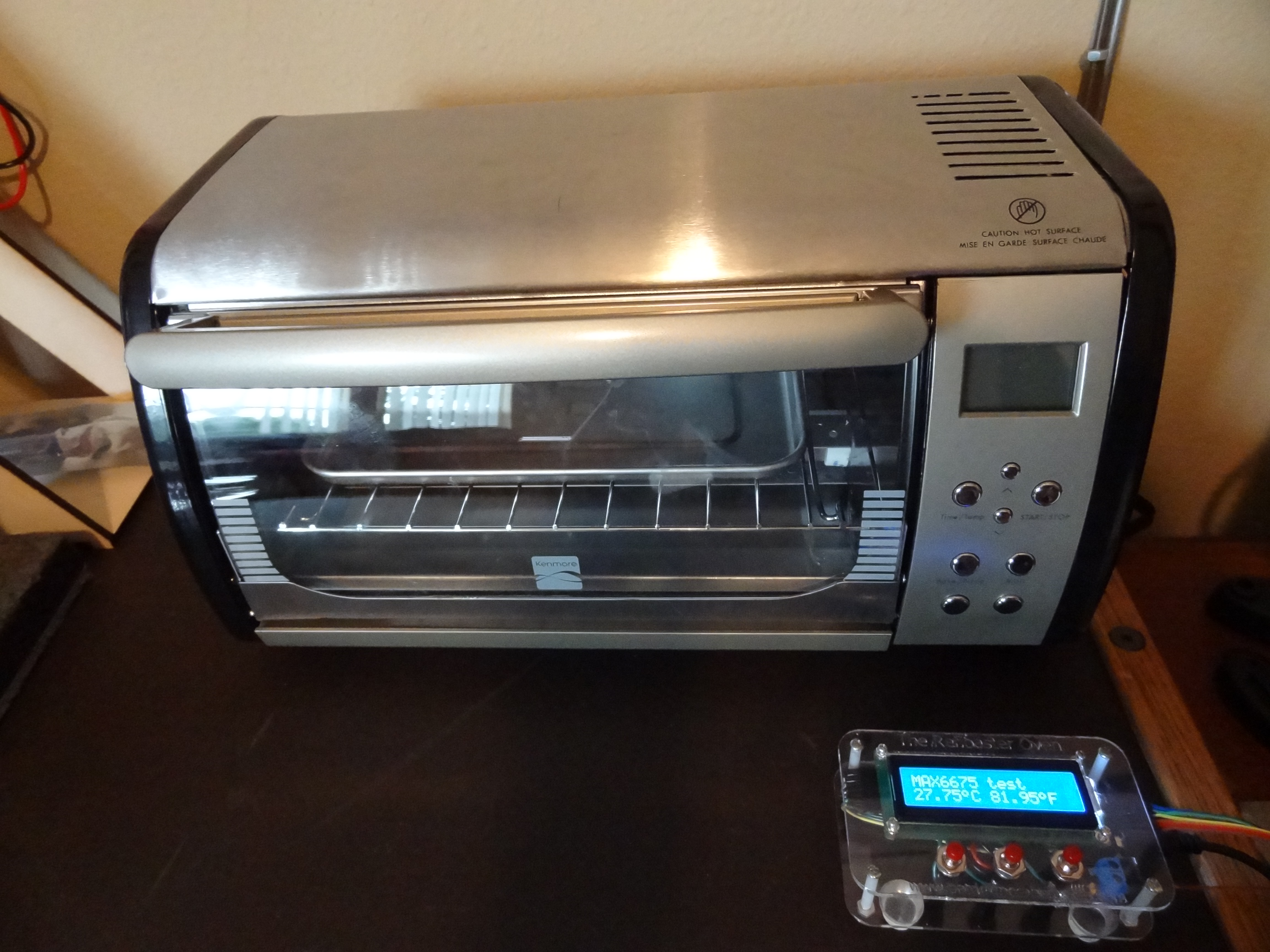
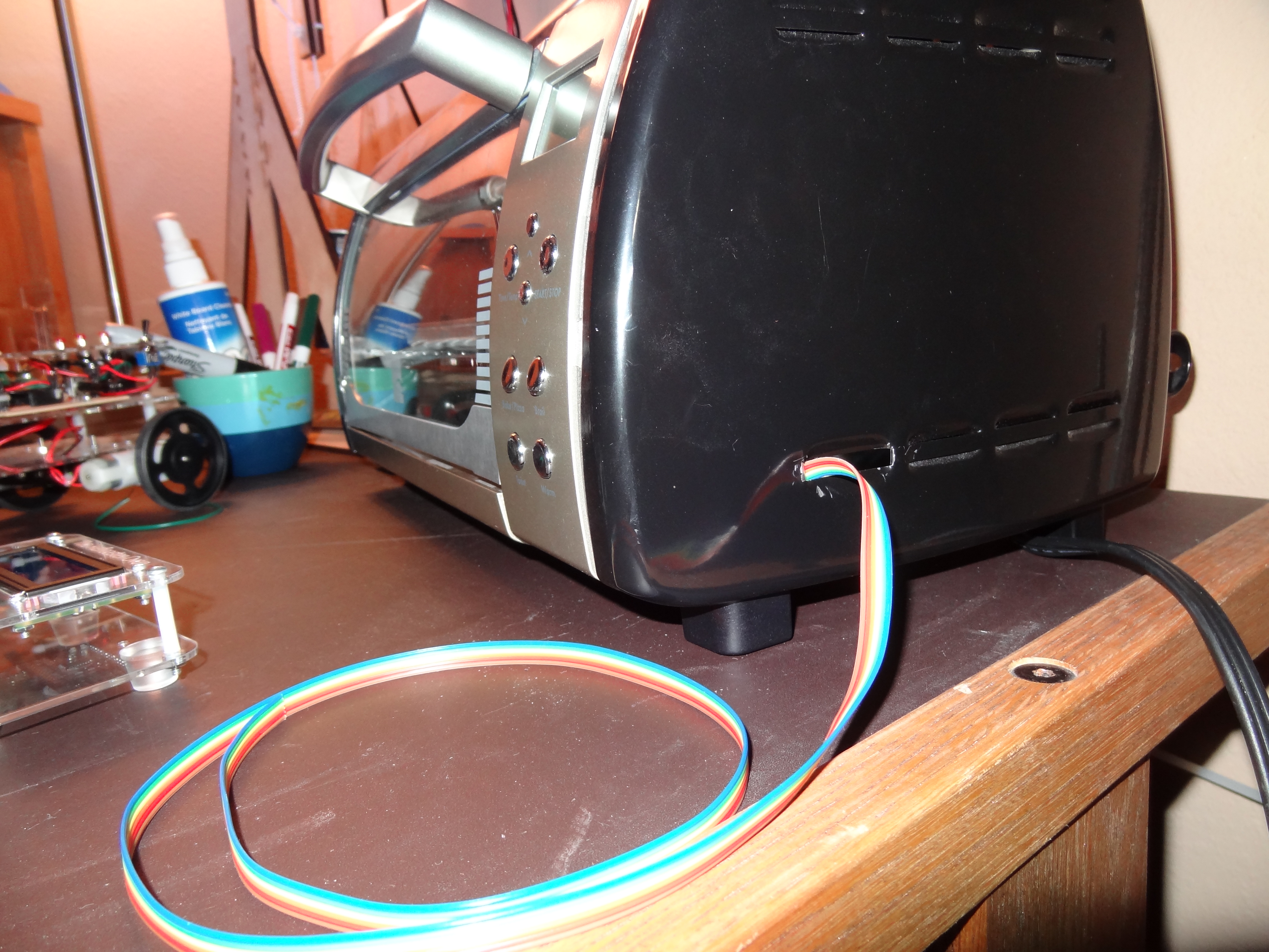
This is a Kenmore digital toaster. What I liked about this was the ability to change the temperature with the buttons. You will see later how this comes into play when I start taking the toaster apart and wiring it for my use. Other than that, it is a pretty normally toaster oven I suppose.
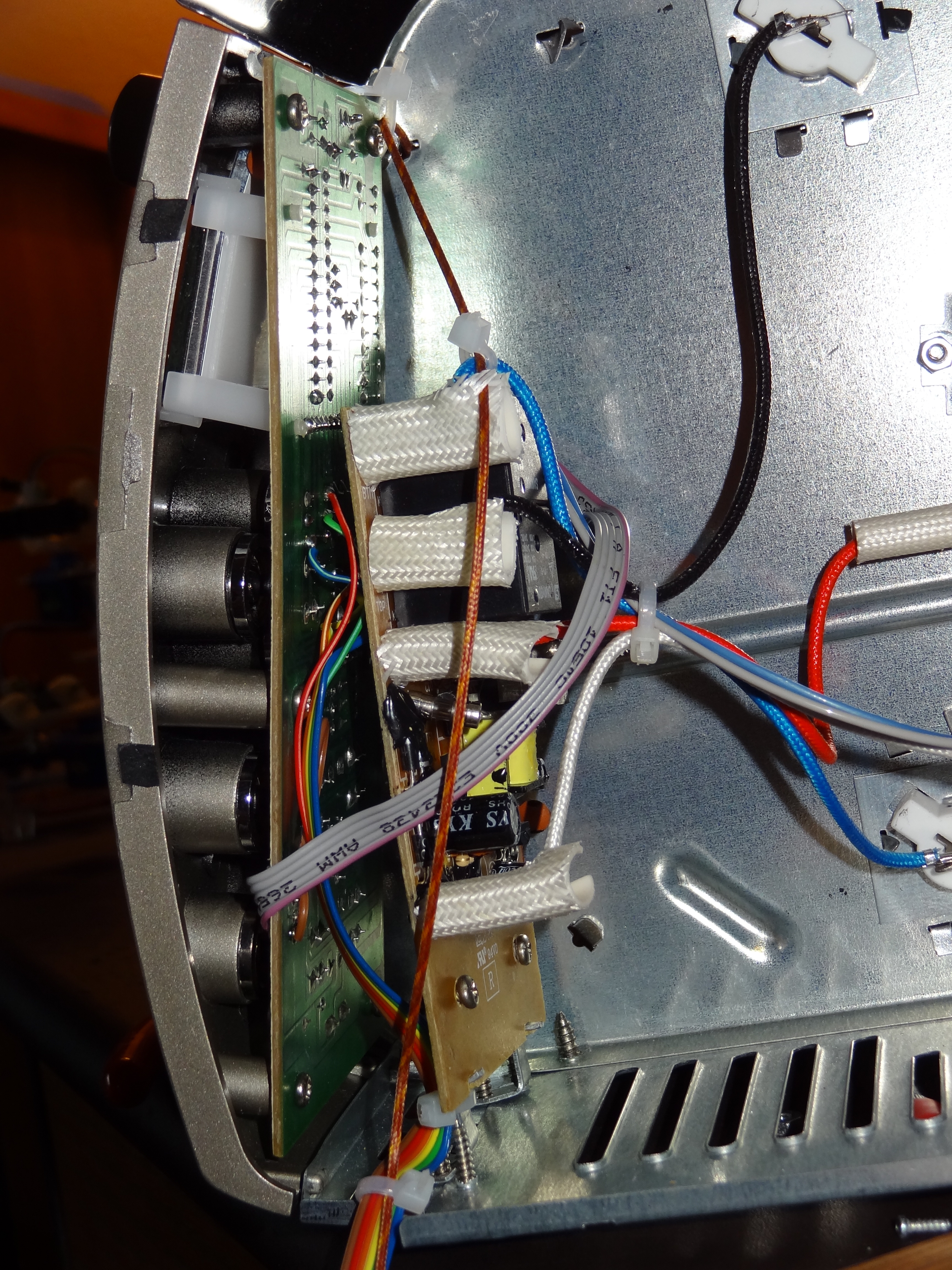
When it is taken apart to where the circuit boards are accessible it looks like what you see below. There is, however, a ribbon cable in the first picture that I added. I will explain that next.
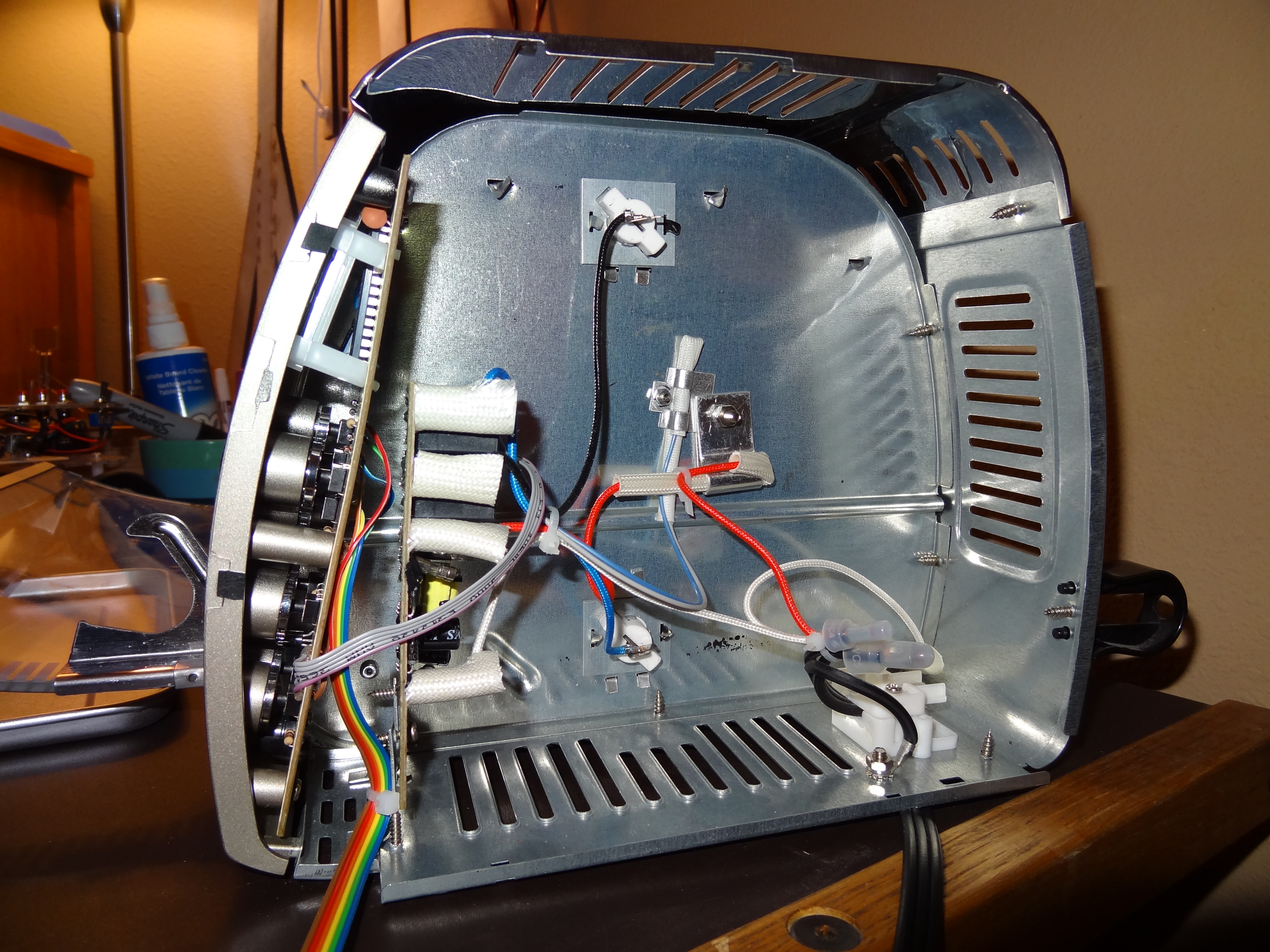
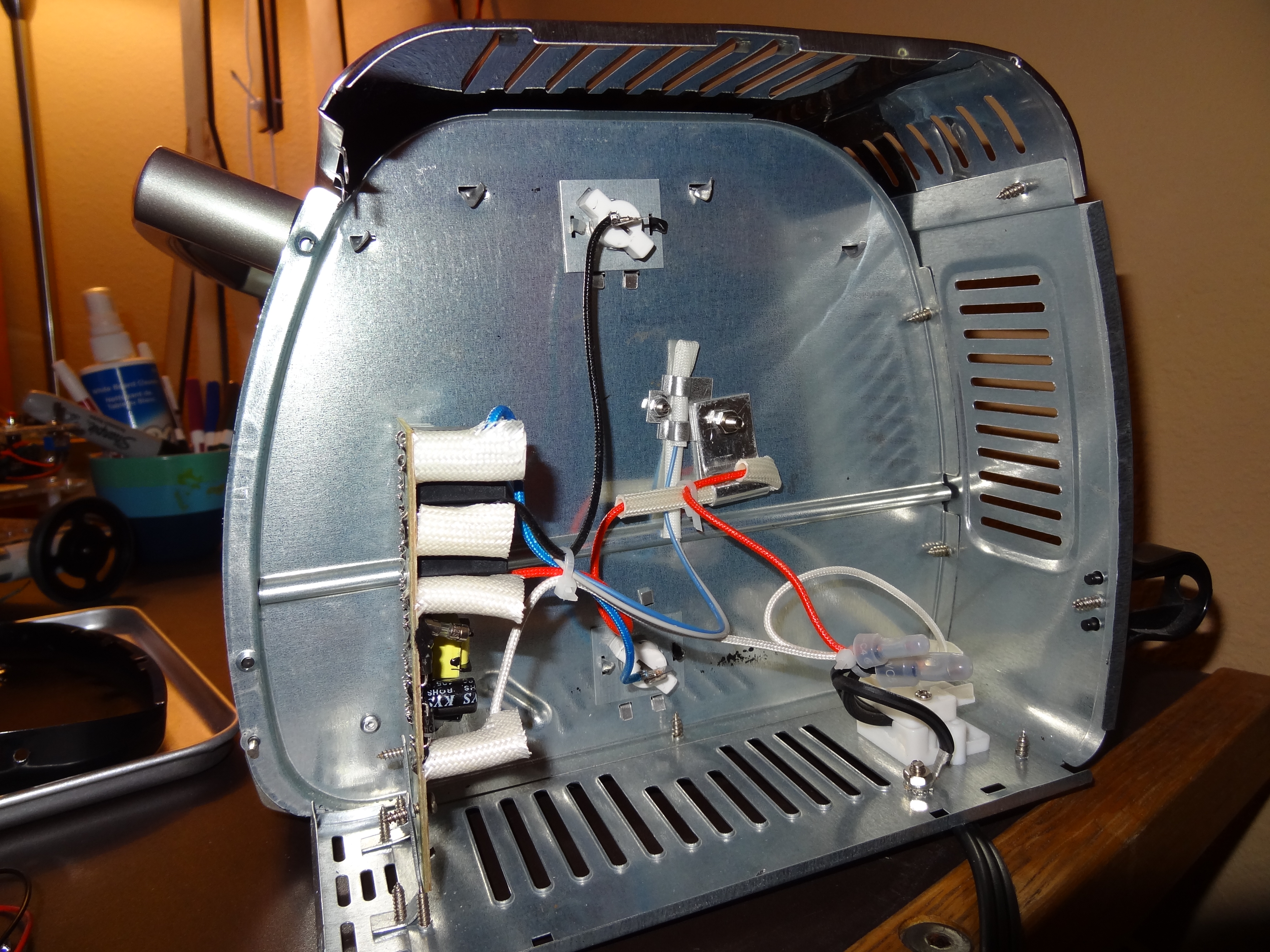
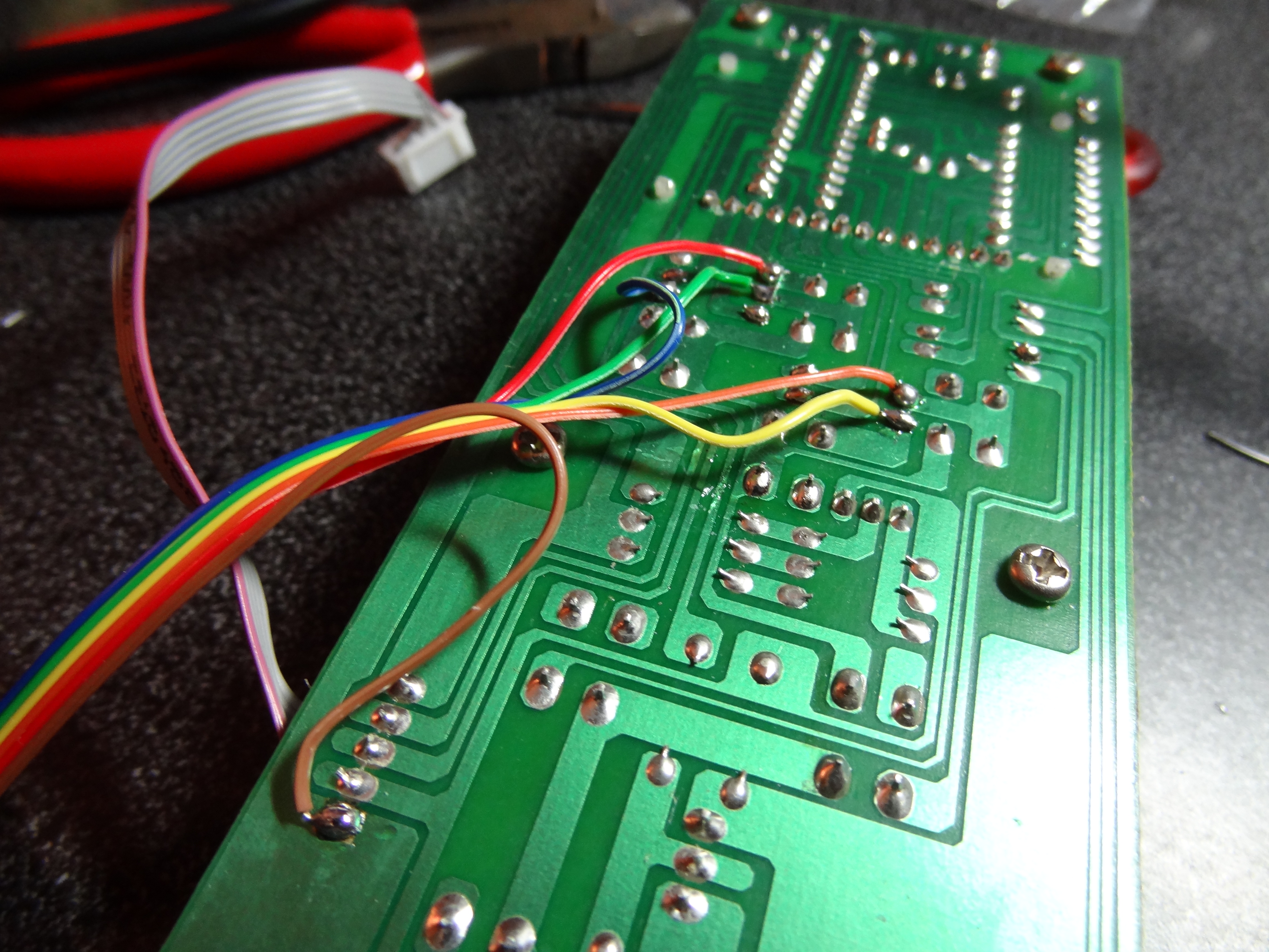
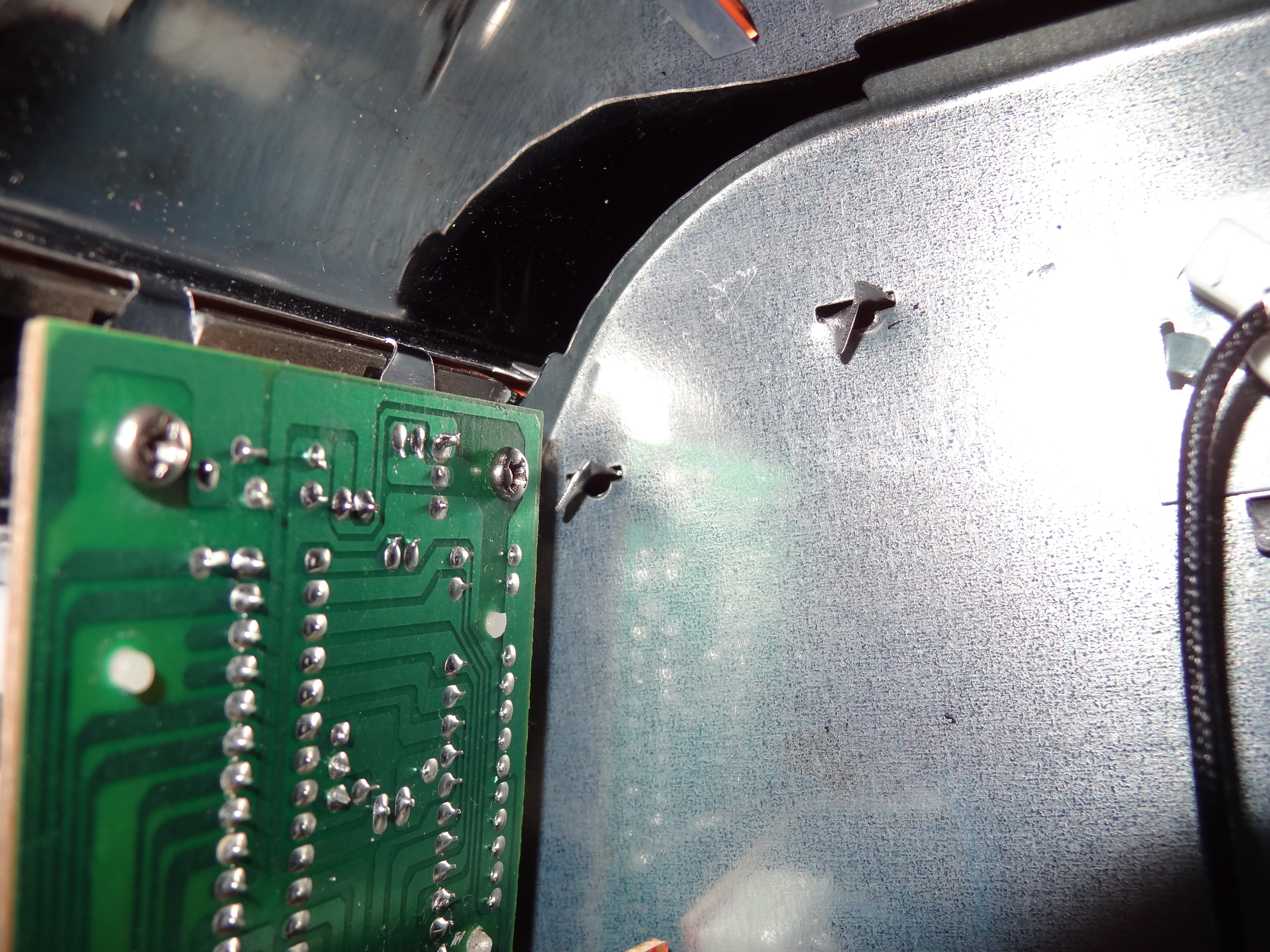
I removed the front panel that contains the buttons, LCD, and micro-controller. I was able to follow the traces and find out where the 2 sides of each button were and which one was the input of the button and which one was the output. The idea behind the control of this is to add wires to the input and output of the buttons. I can then use a transistor connected to a micro-controller to act as these buttons would if pressed. I had a total of 6 connections I had to make. The first one was the common input of all the buttons. The second one was ground, which needs to be shared. The other connections go to the different outputs of the buttons which lead to inputs of the toaster oven’s micro-controller. The buttons that I needed control of were: temperature up, temperature down, temperature/time select, start/stop. You can see images of those connections I made below.
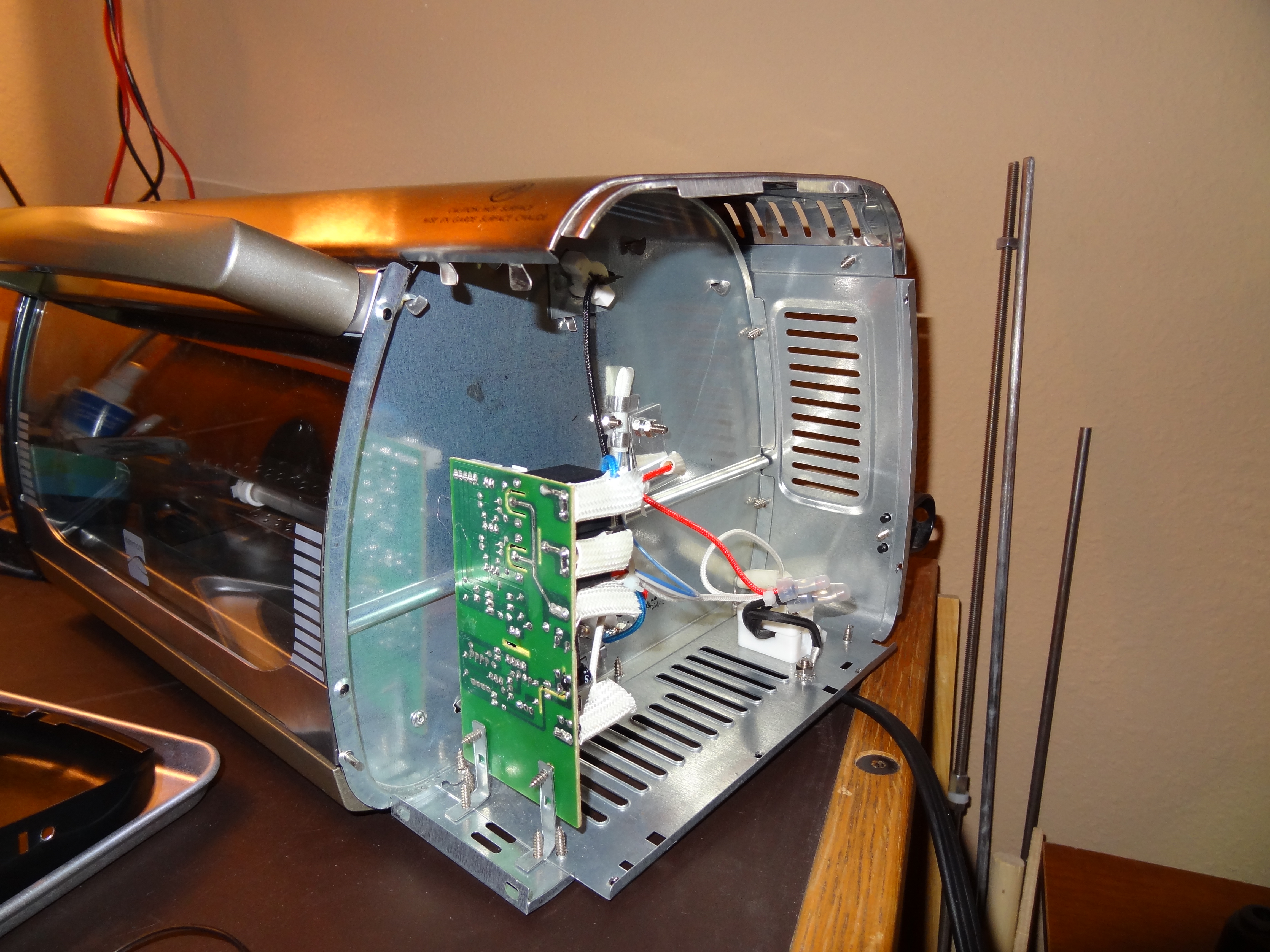
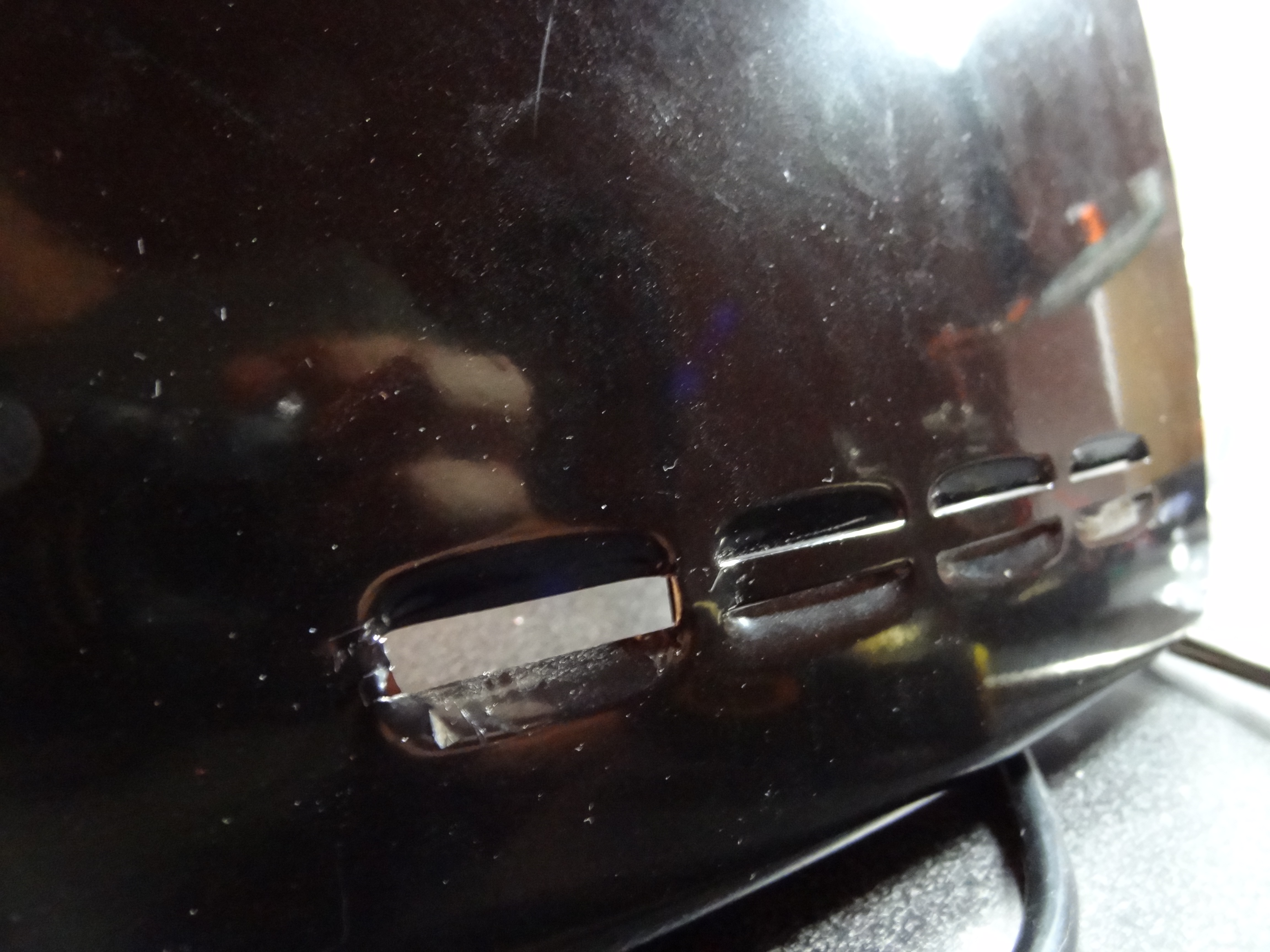
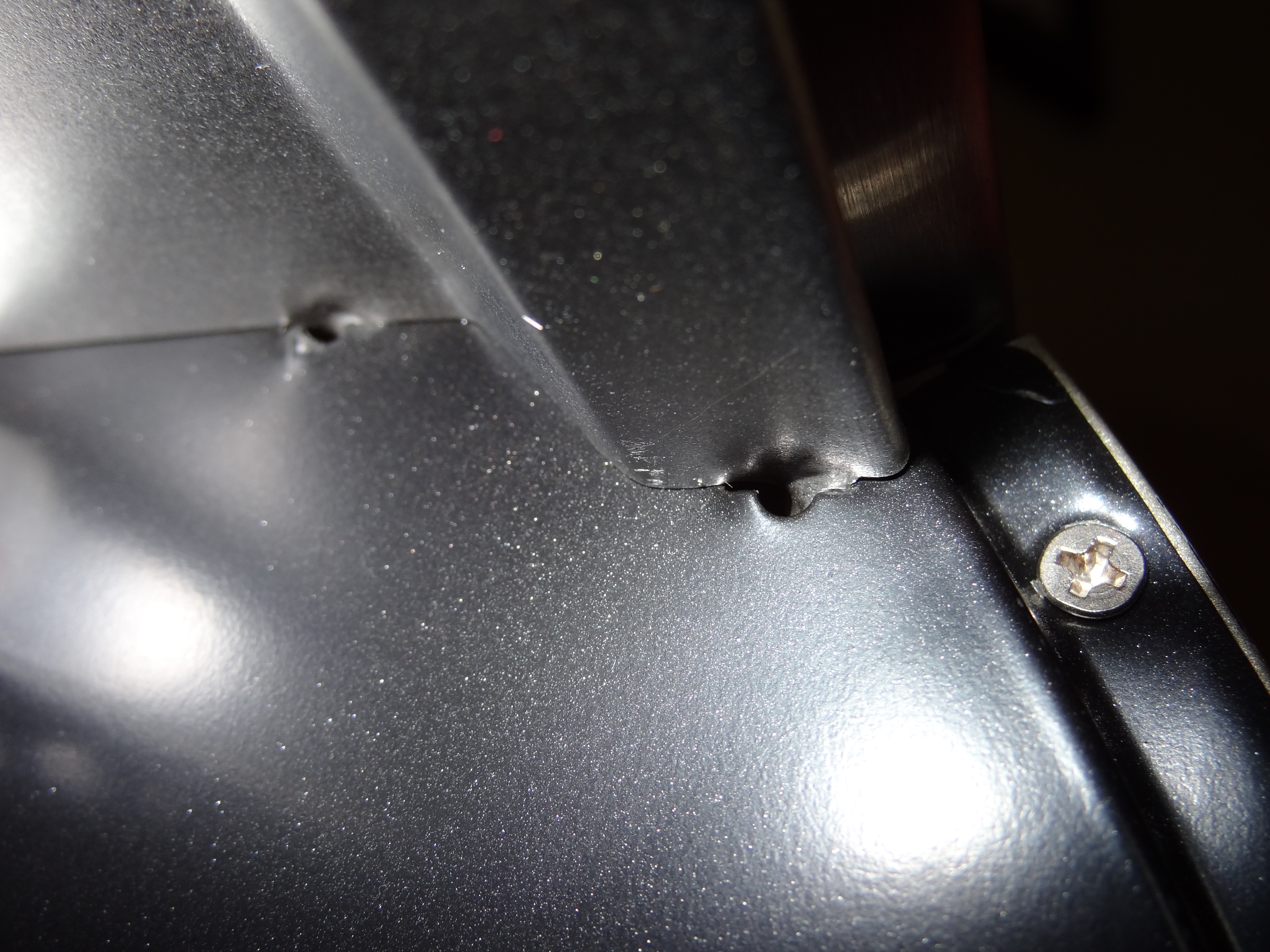
I needed a way to run the ribbon cable outside of the toaster so I cut a tab off the side wall of the toaster.
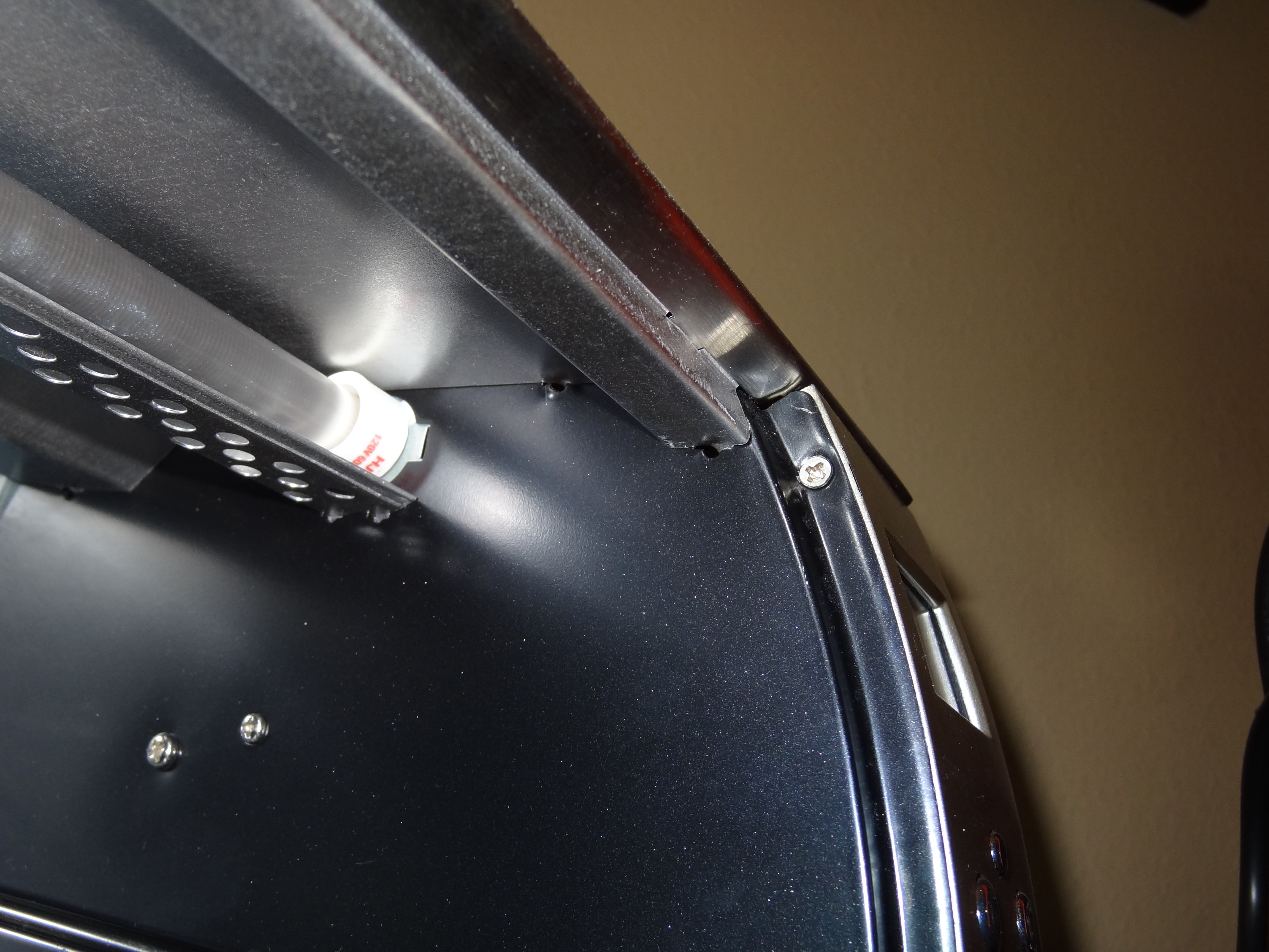
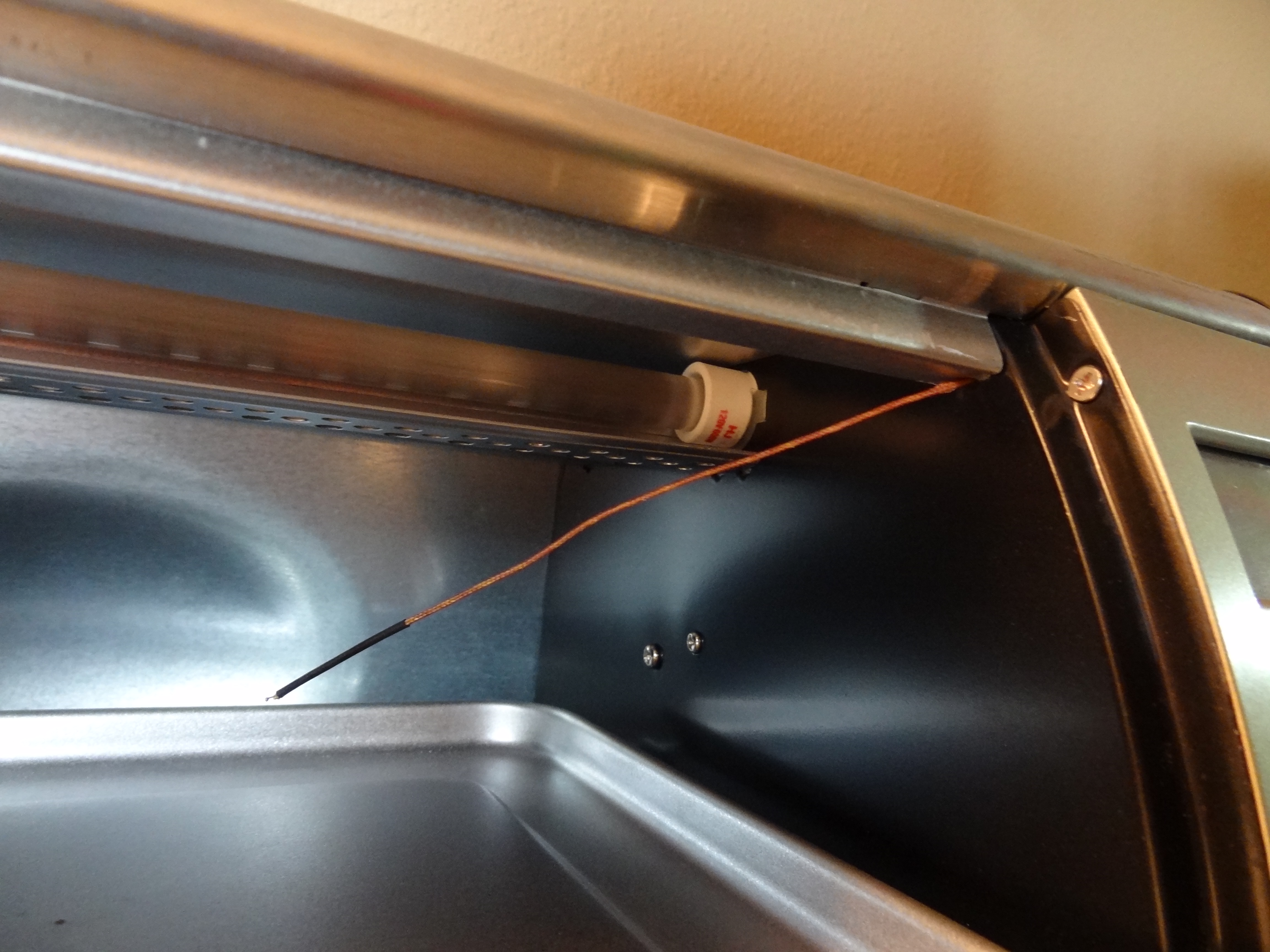
When my thermocouple arrived I found myself taking the toaster oven apart again. The thermocouple will be used by my controller to read the temperature inside the toaster oven. I found a small hole near the top of the toaster oven that the thermocouple would fit through. So I took the toaster oven apart one last time to run the thermocouple wire through this hole and out the same place the ribbon cable exits.
Laser Cut Parts
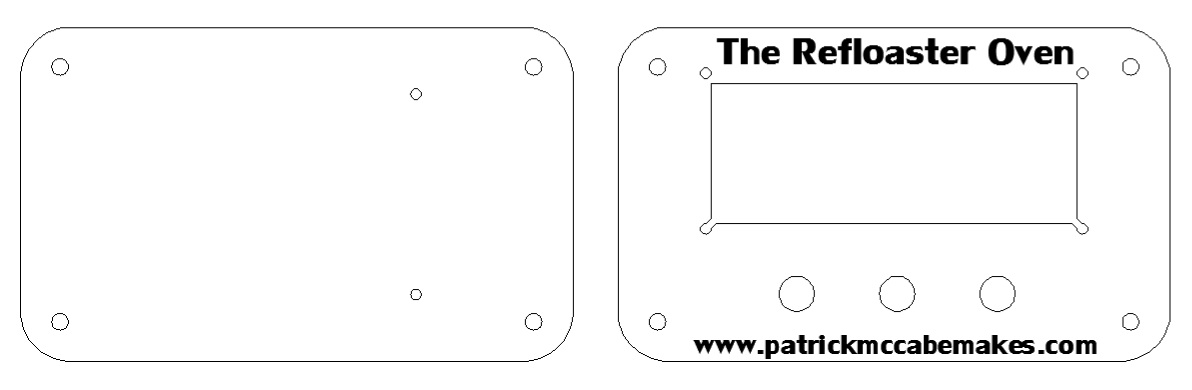
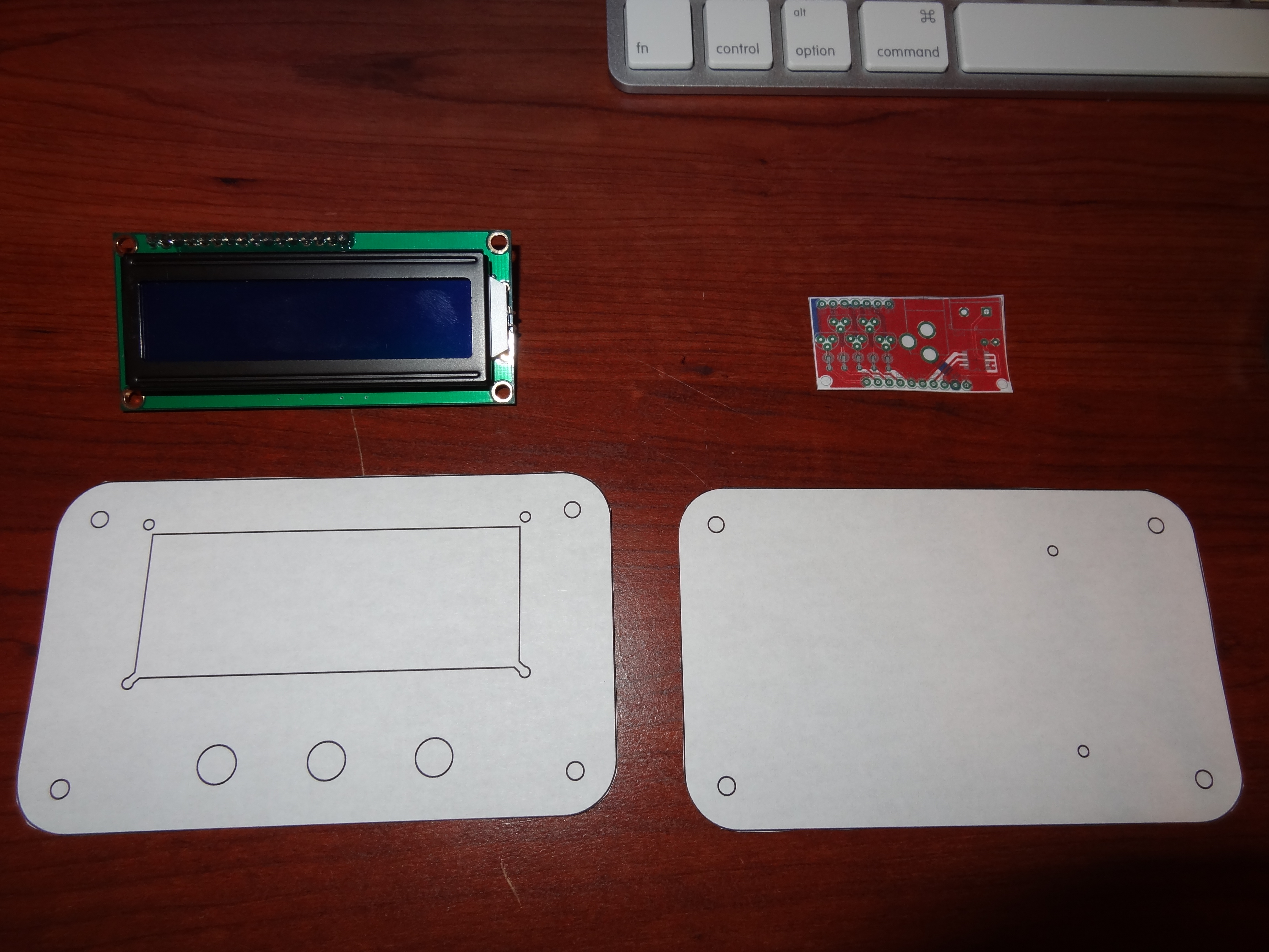
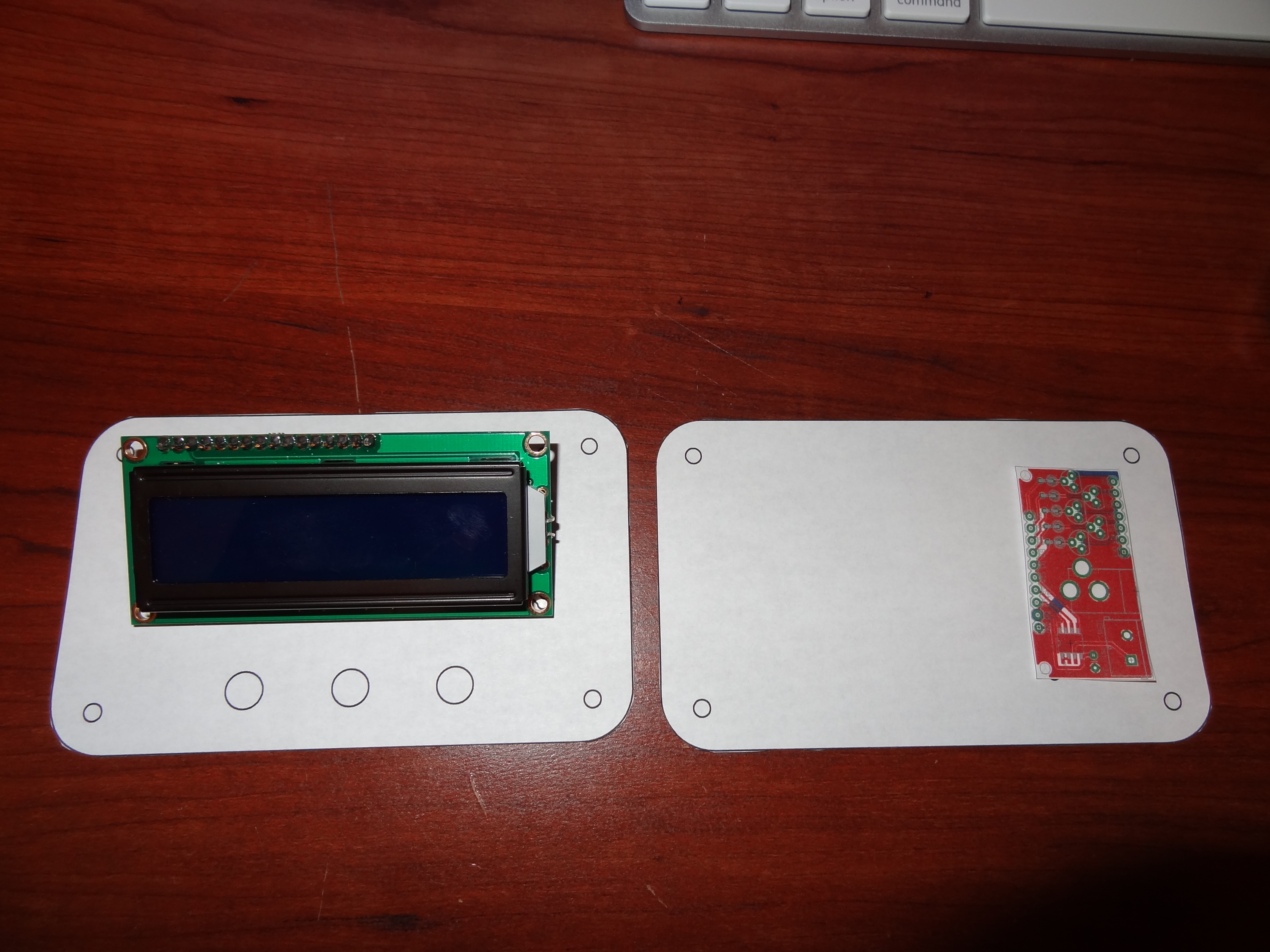
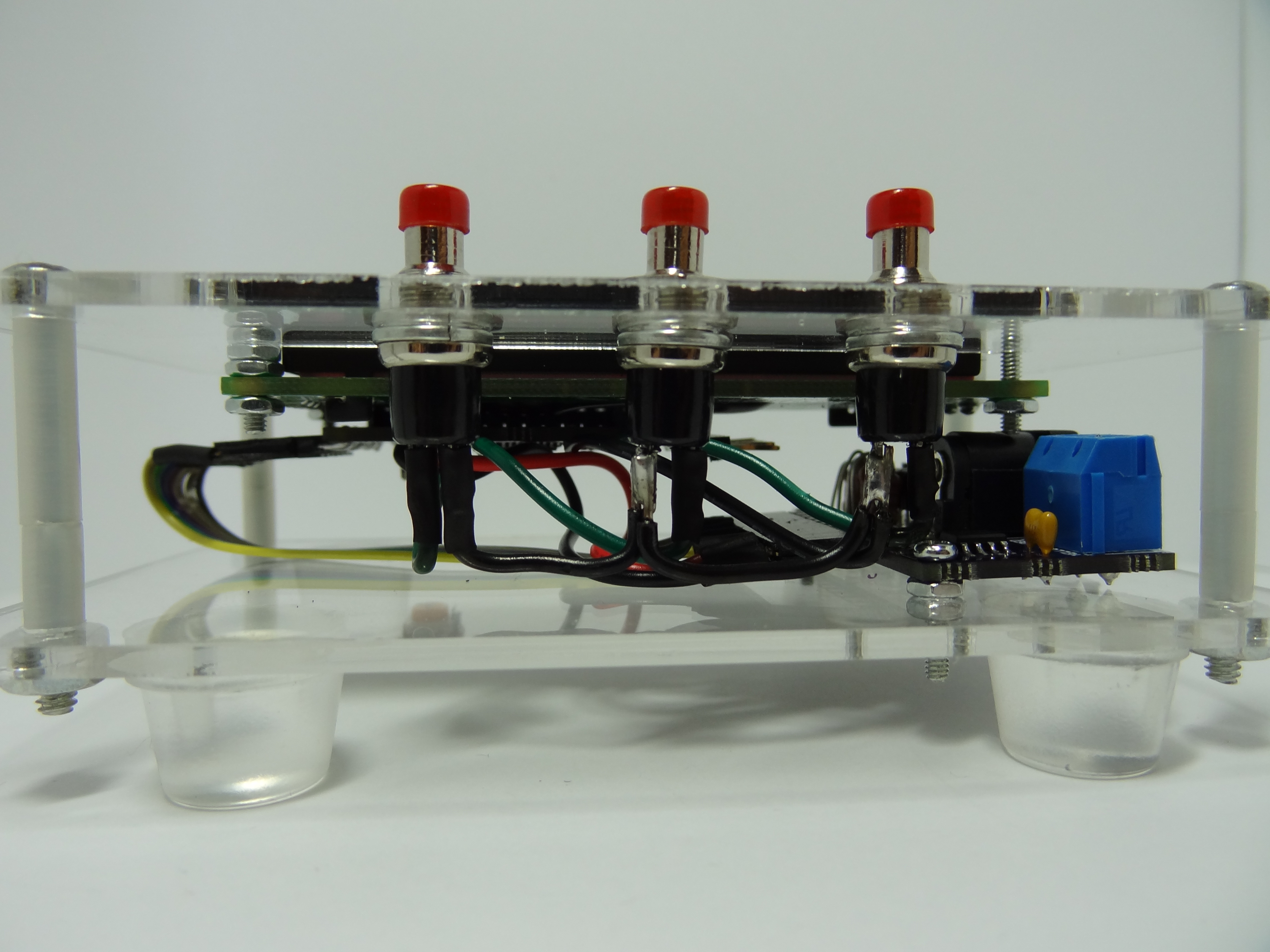
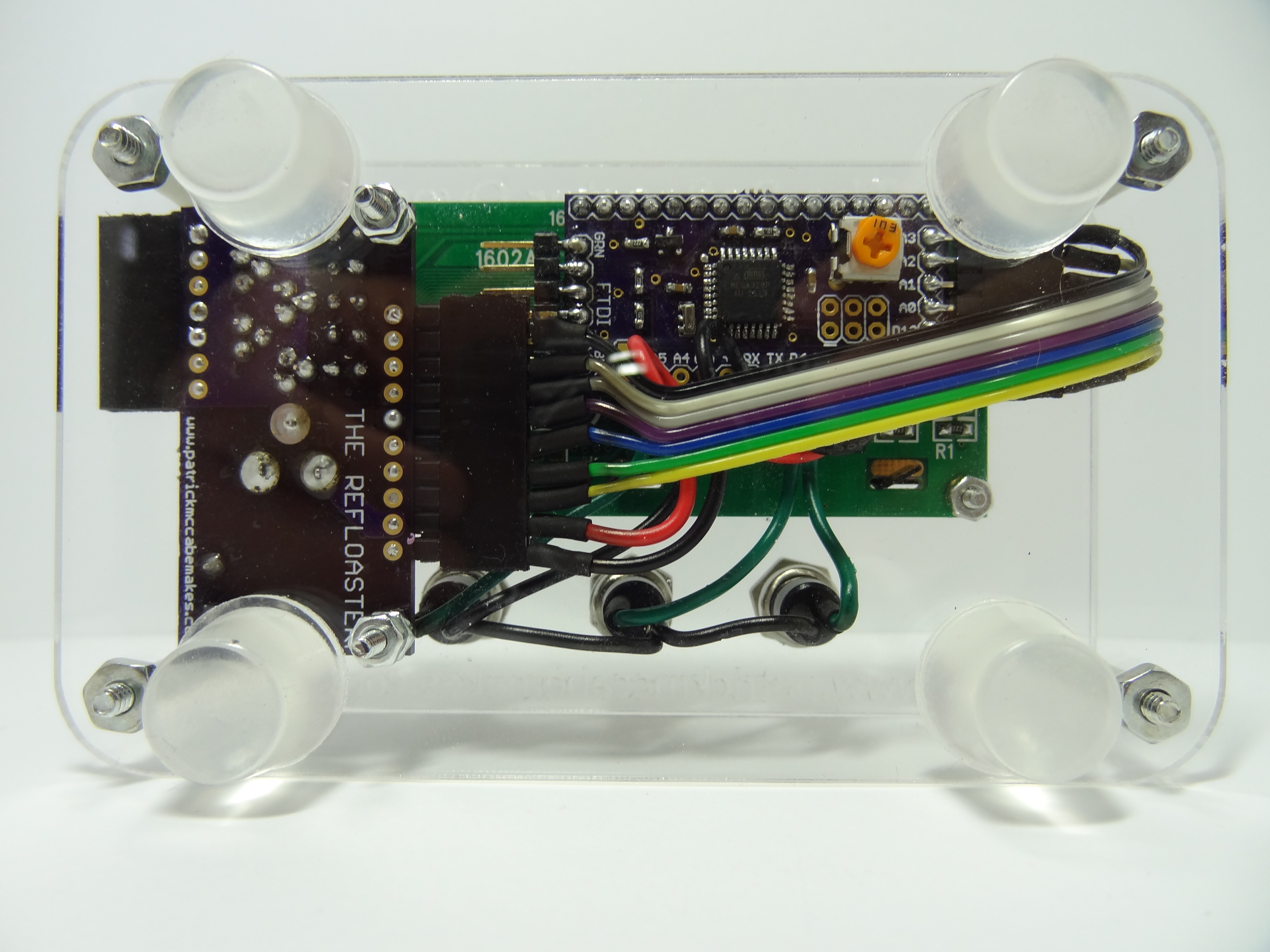
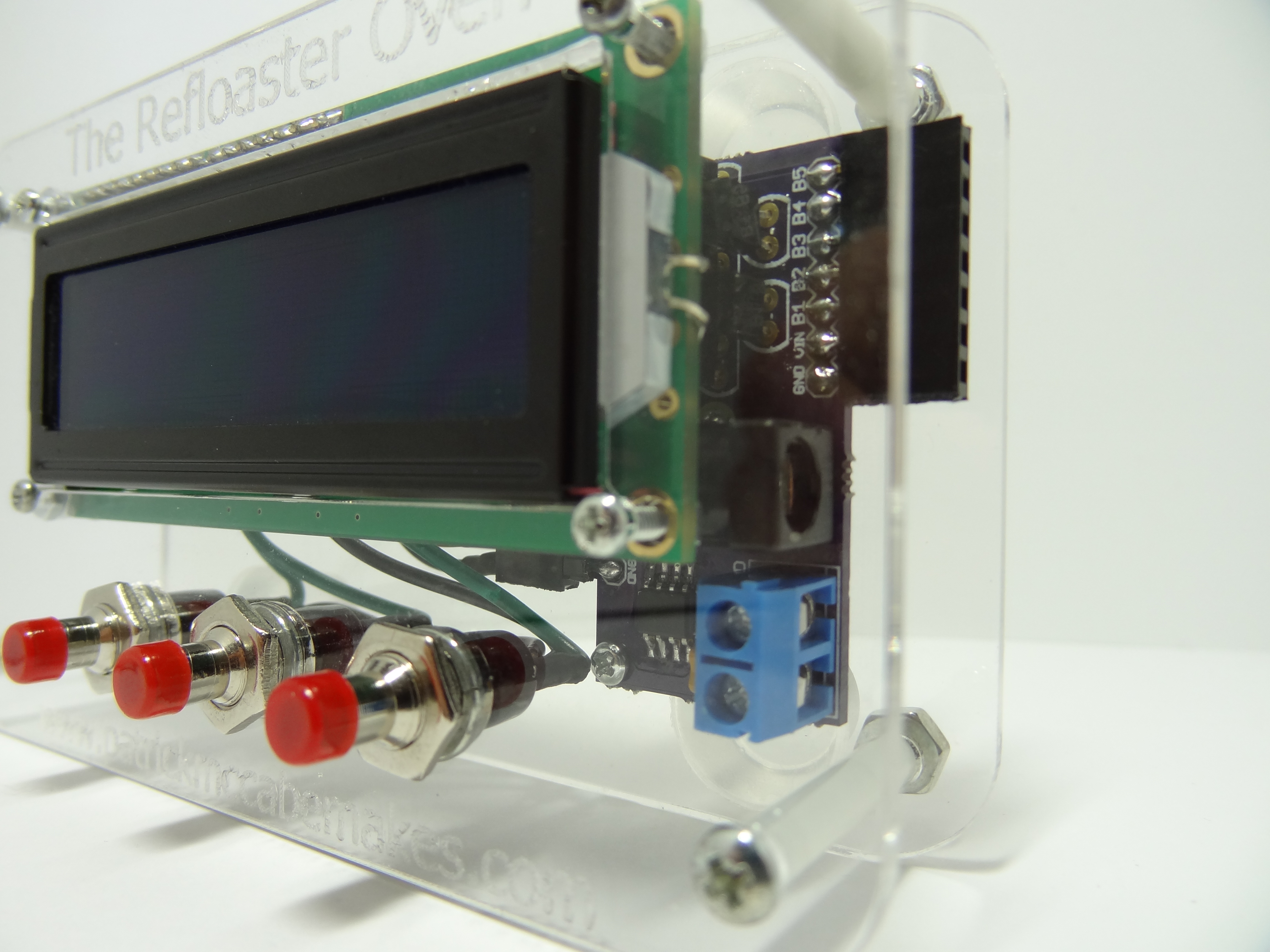
Like everything else I have laser cut, these plates were designed in AutoCAD by me. I then cut them out on an acrylic sheet using my school’s laser cutter. The design is basically a modified version of my Controller V2. It has a cutout out for a LCD screen and 3 holes for push buttons. It also has 2 holes on the bottom plate for mounting a PCB I designed for this project. The four holes in the corners connect the 2 plates together using bolts and spacers.
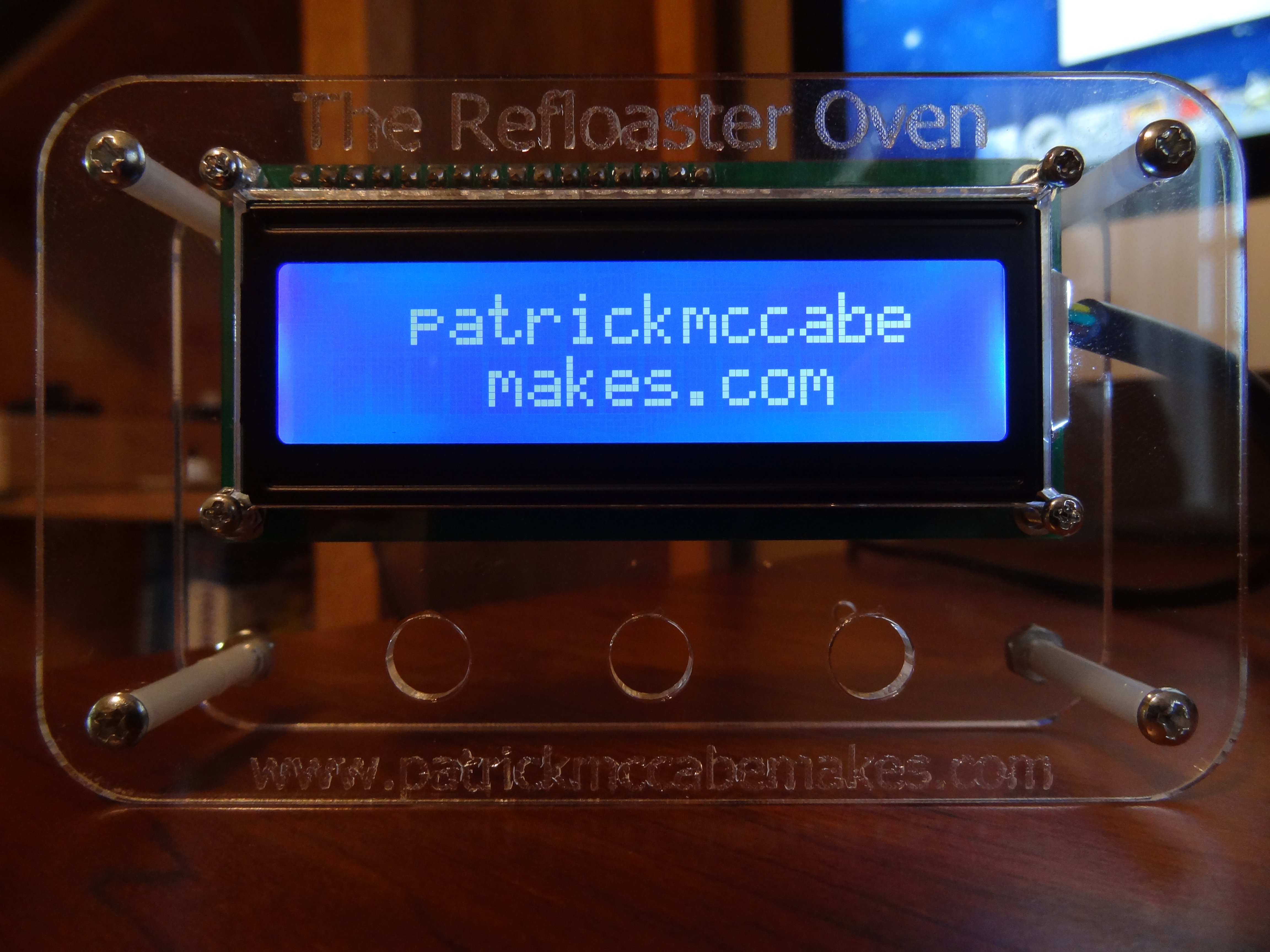
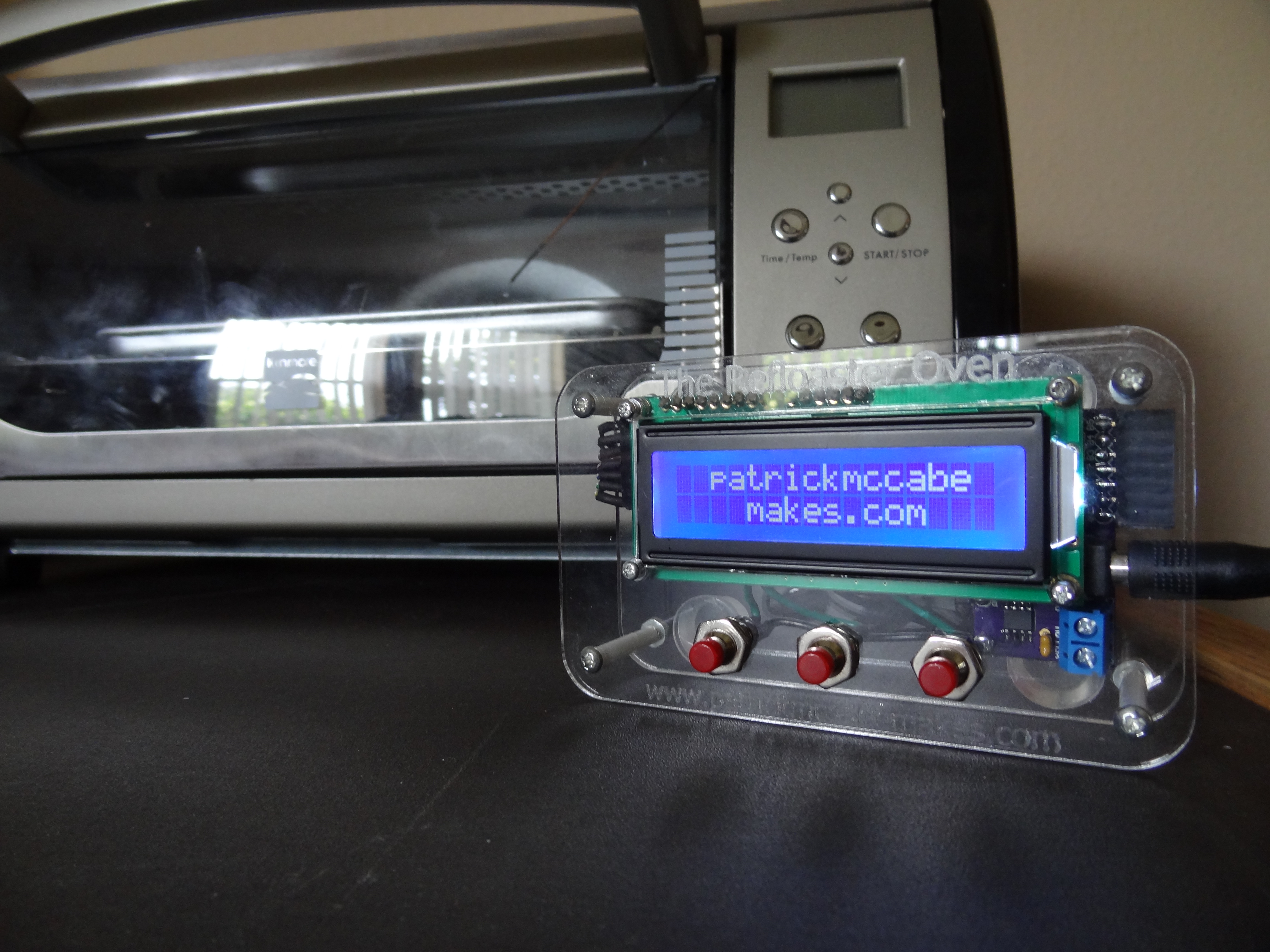
The Display
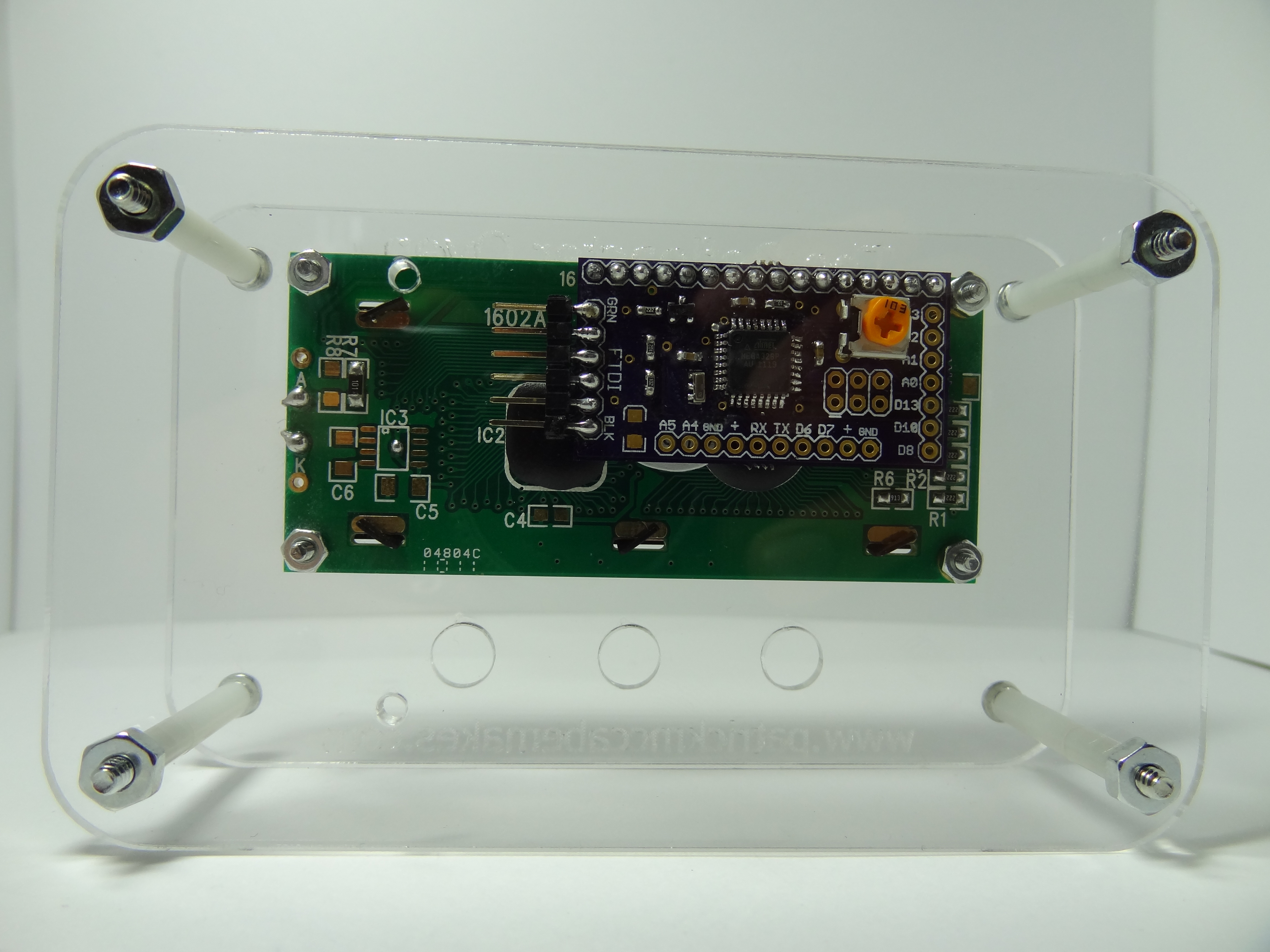
The Refloaster Oven’s controller has a 16x2 LCD screen. I used one of my SMD ezLCDuinos to control the LCD and to act as the main micro-controller of the whole project. You can read about the functionality of the ezLCDuino on its page.
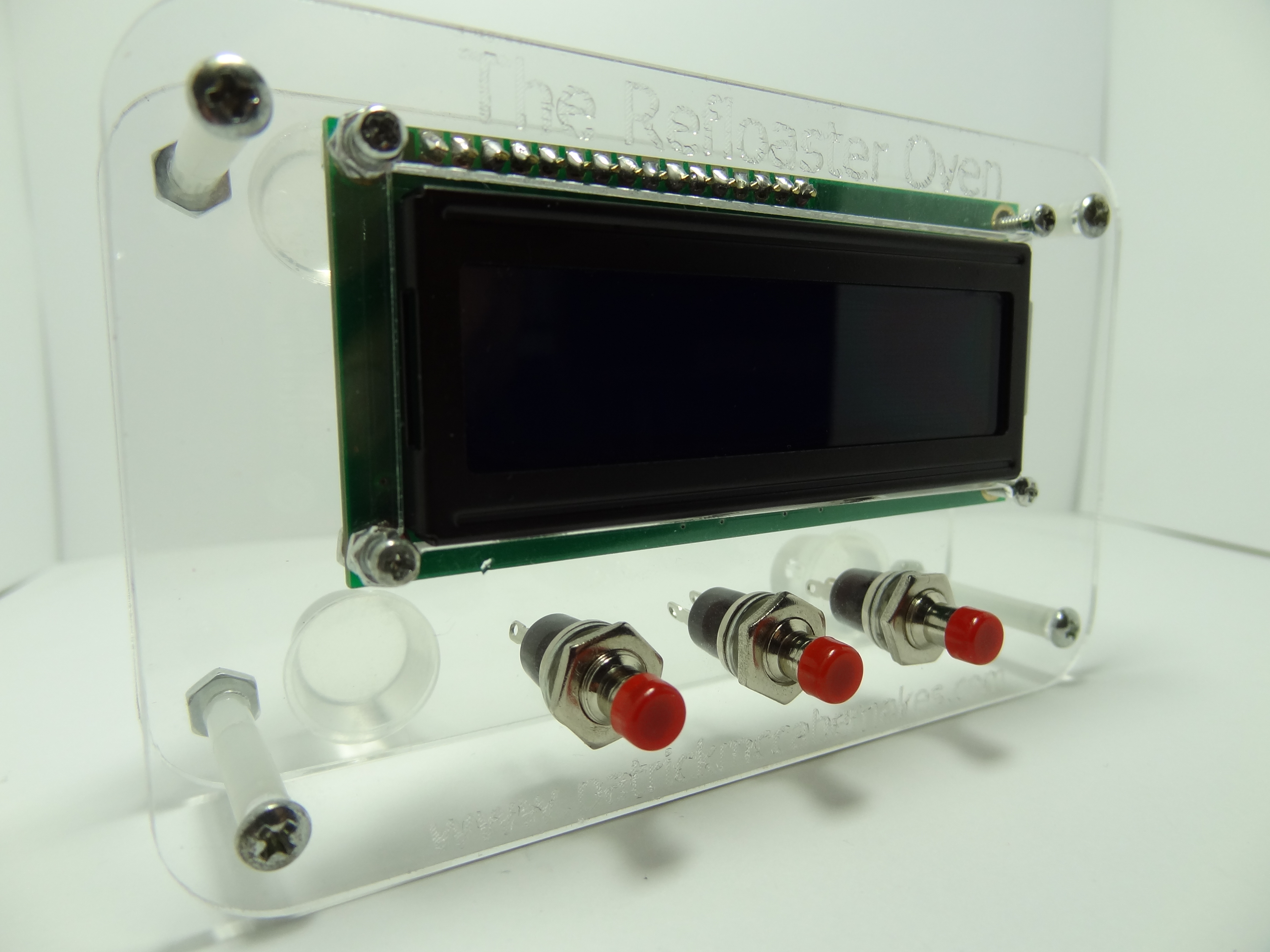
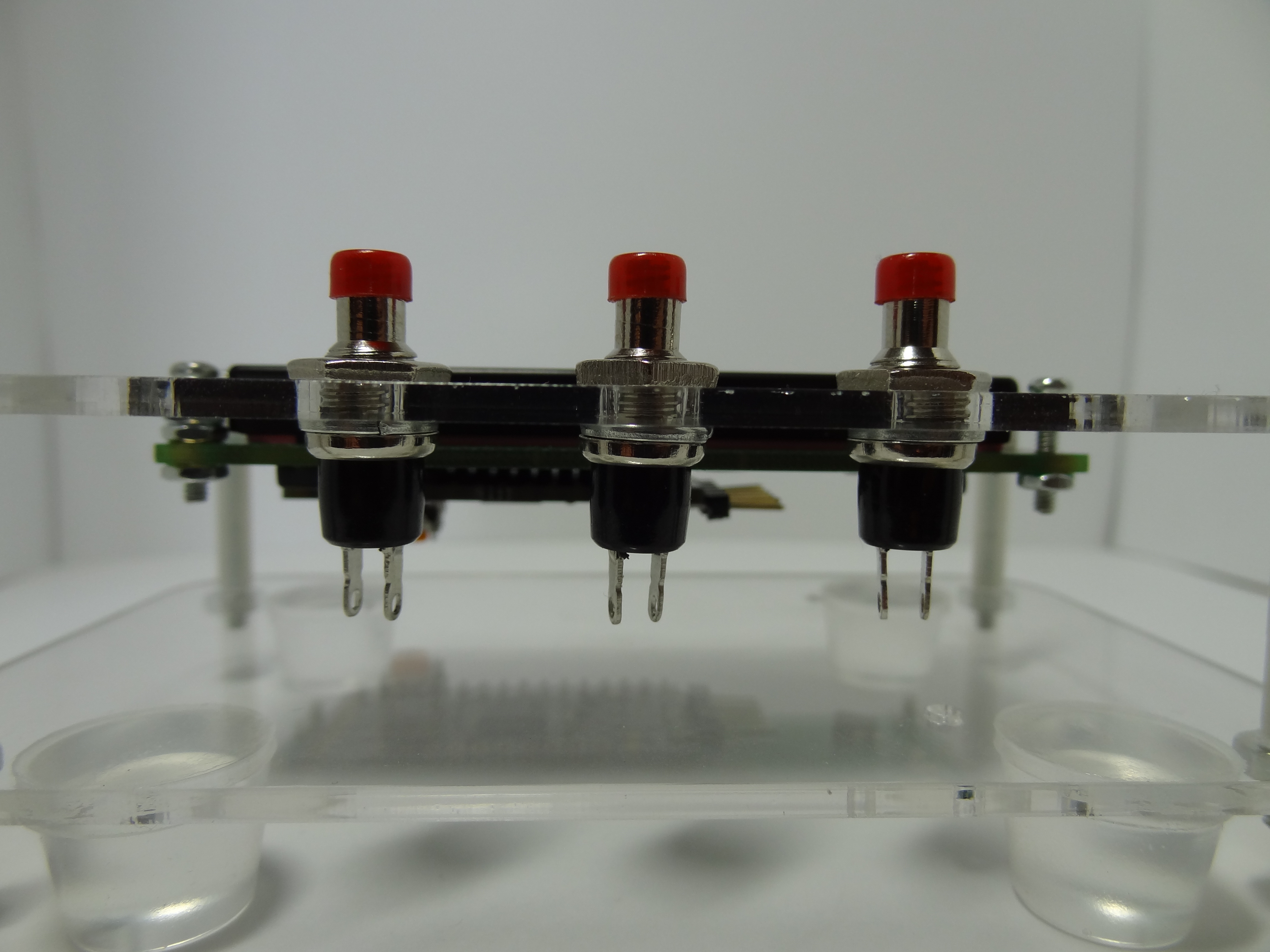
User Input
There are 3 buttons that will be used for any user input needed by the program. These will be used to navigate the menu and change settings in the program.
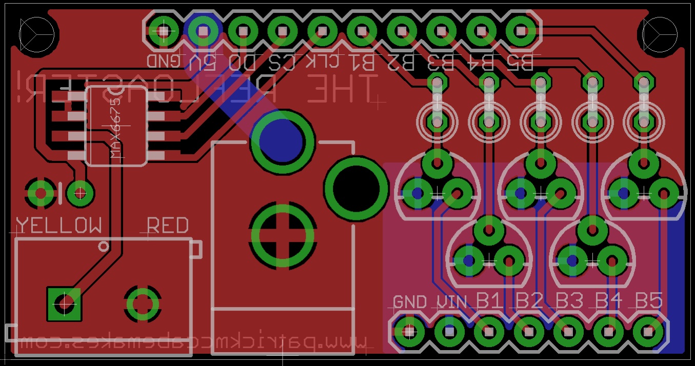
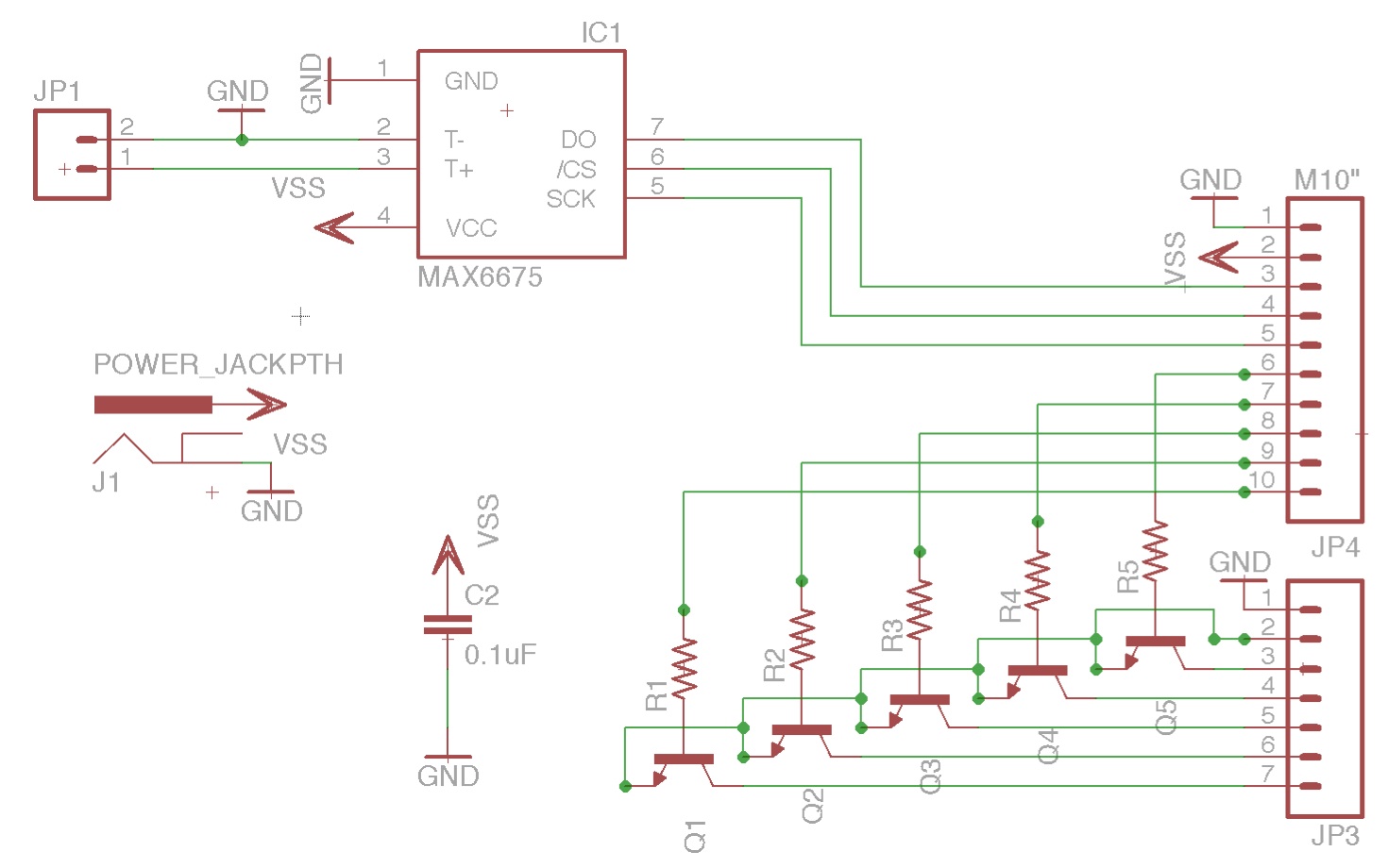
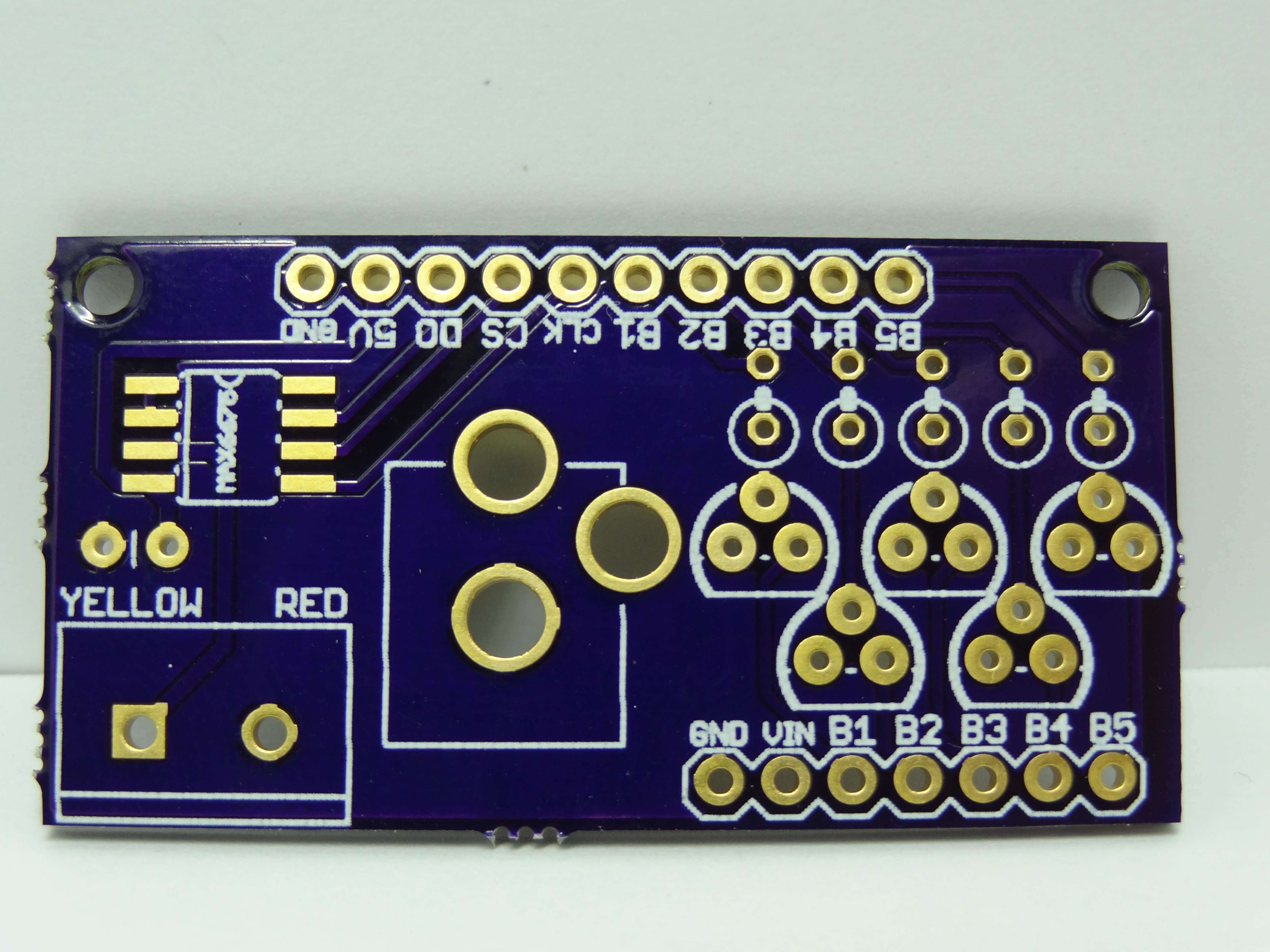
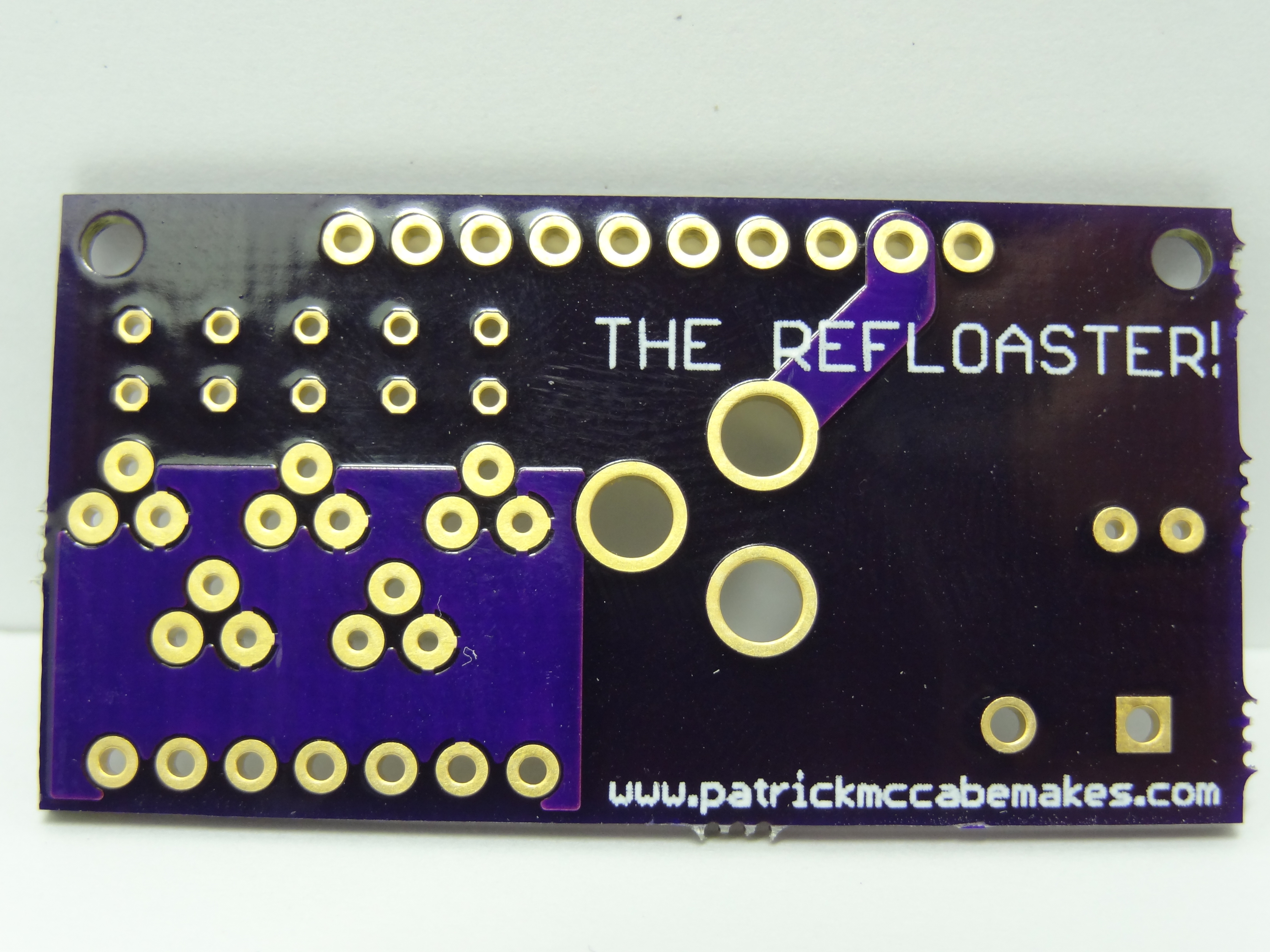
Secondary Circuit Board
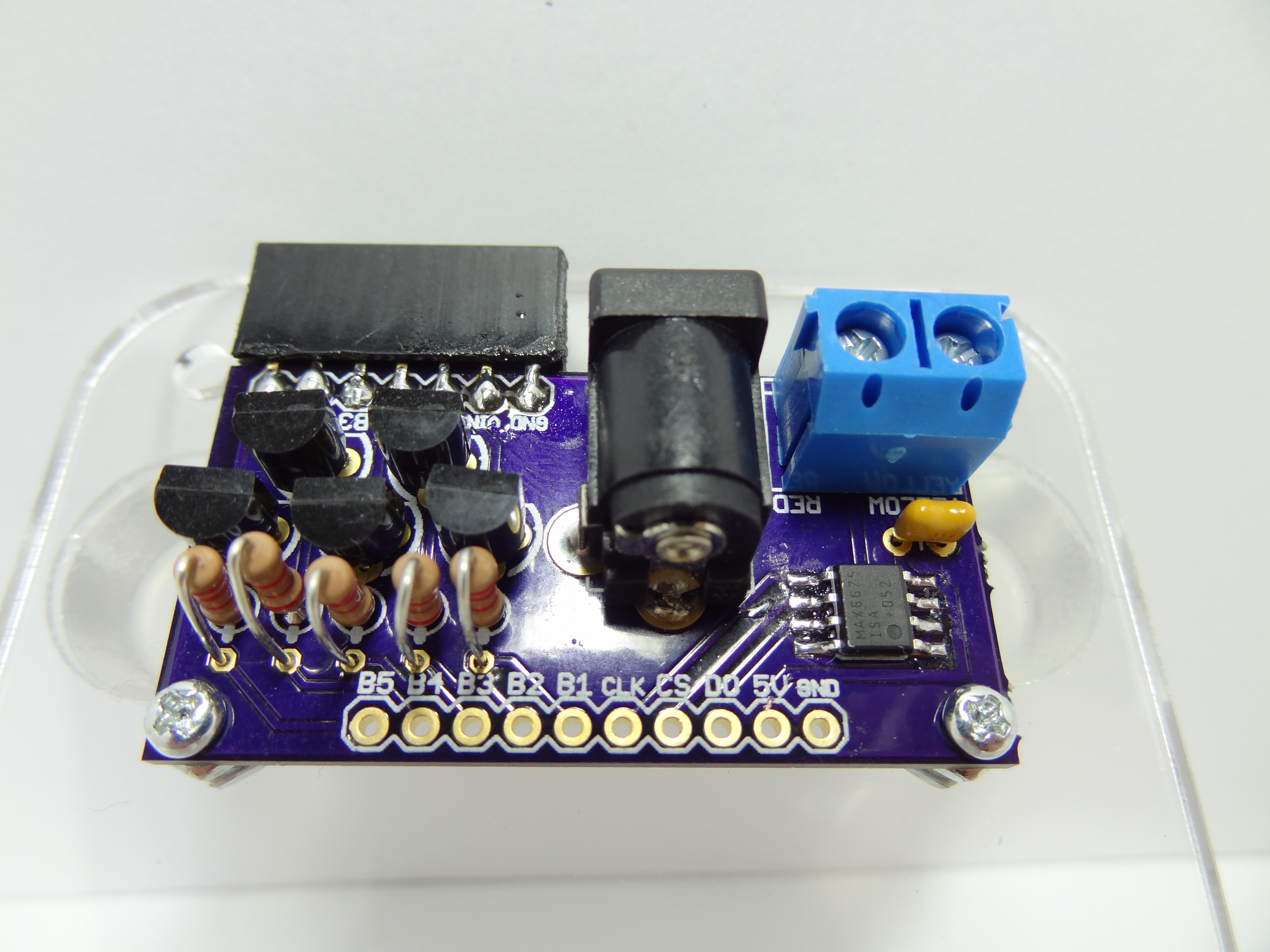
I designed another PCB for this project to add the functionality I needed that the ezLCDuino lacked. This includes transistors and a thermocouple amplifier. Click here to download the EagleCAD files for this board.
Parts List:
- 5 - 2n3904 NPN Transistors
- 5 - 2.2k Resistors
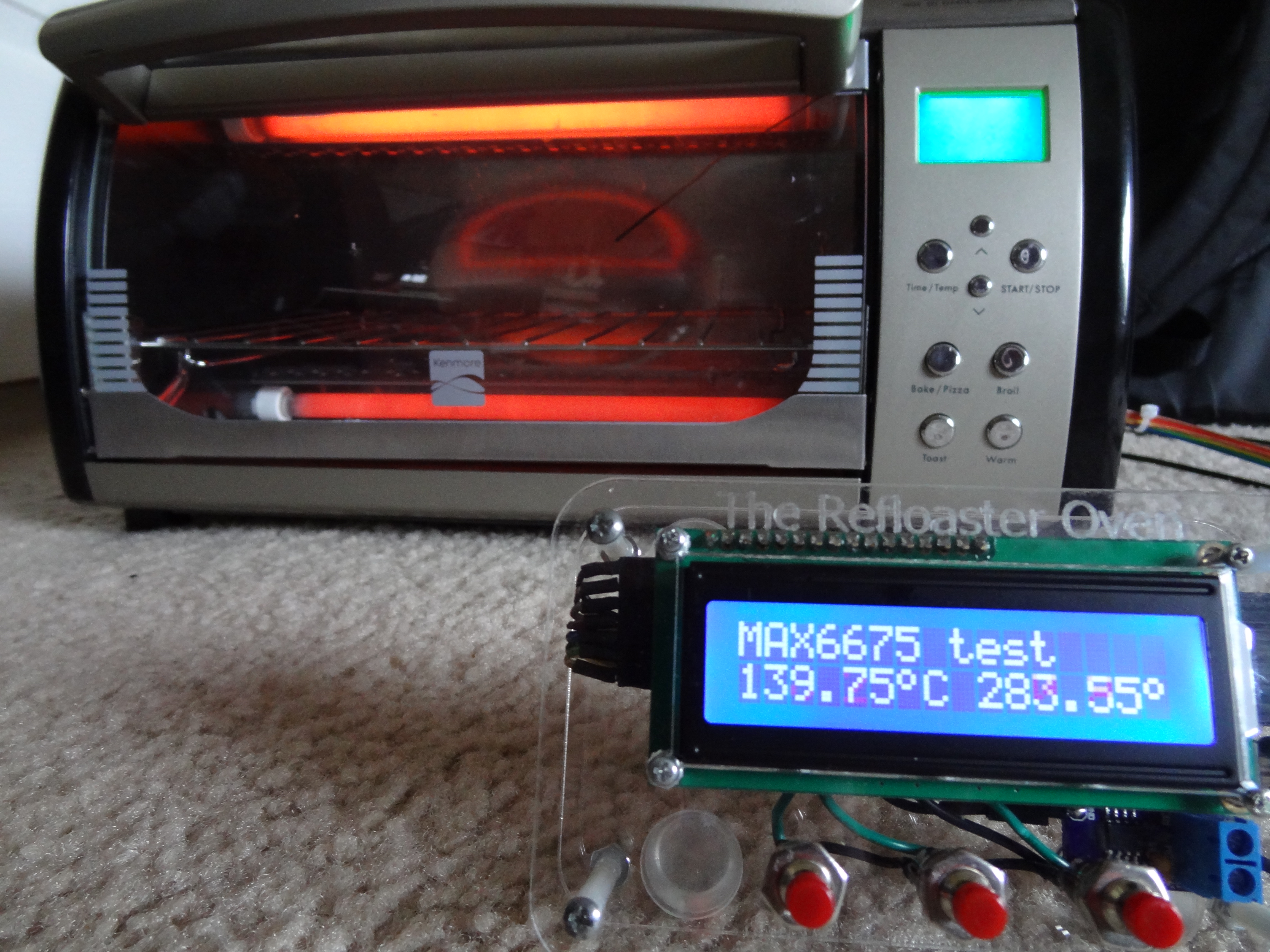
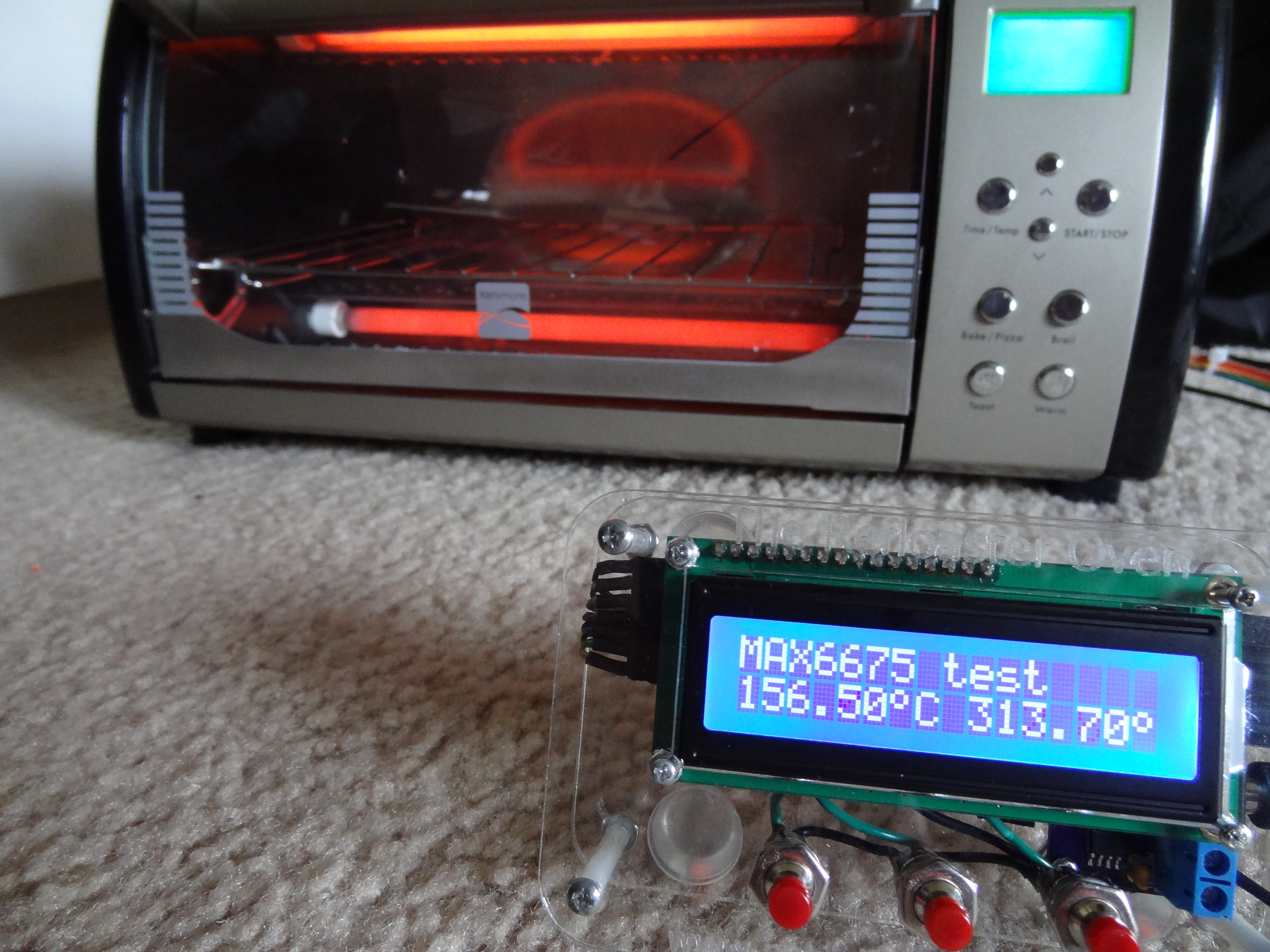
- 1 - MAX6675 Thermocouple Amplifier IC
- 1 - 0.1uf Ceramic Capacitor
- 1 - Barrel Jack Power Connector
- 1 - 2 Pin Screw Terminal
- 1 - Row of Female Headers
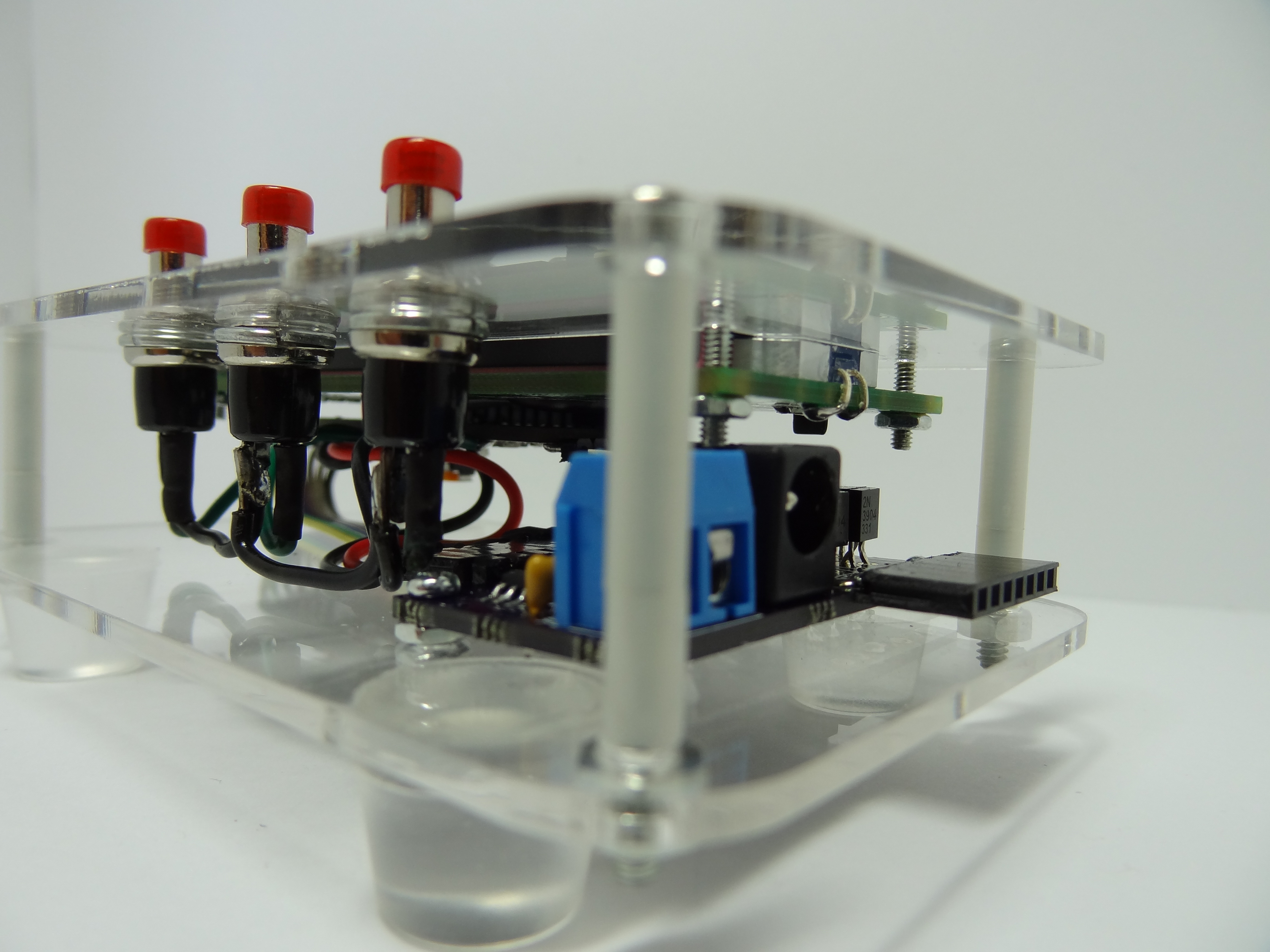
Final Assembly
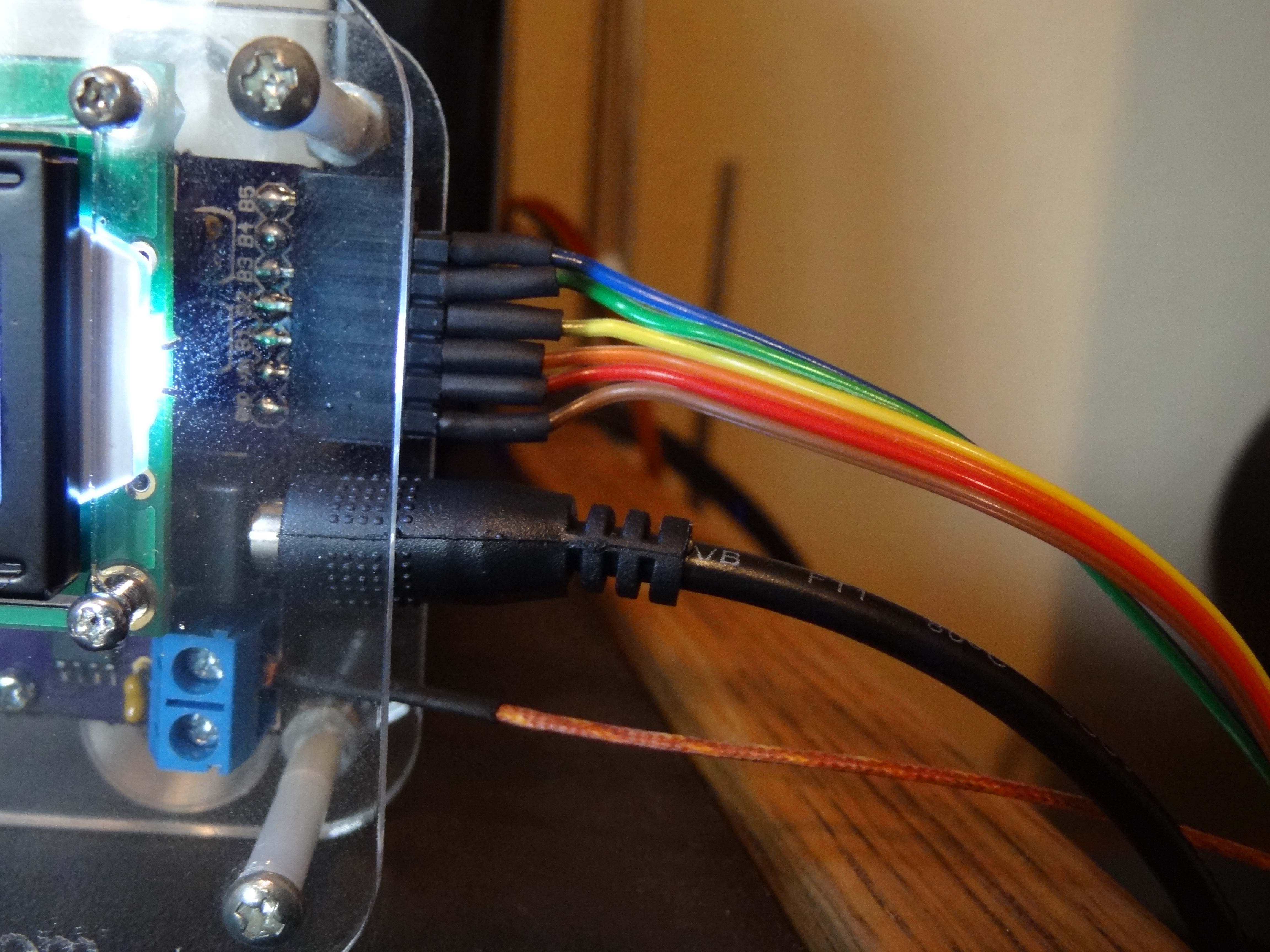
It then just became a matter of finishing the wiring. I had to wire the buttons to ground and to inputs of the ezLCDuino. I used ribbon cable to connect the SPI lines of the thermocouple amplifier and the inputs of the transistors to I/O pins of the ezLCDuino. Finally I just ran 2 more connections to connect power to the ezLCDuino from the barrel jack connector. The thermocouple connects to the secondary board through the screw terminals. Power is supplied by a 5v wall adapter. The ribbon cable from the modified toaster oven plugs into the female connector on the front of the secondary circuit board.

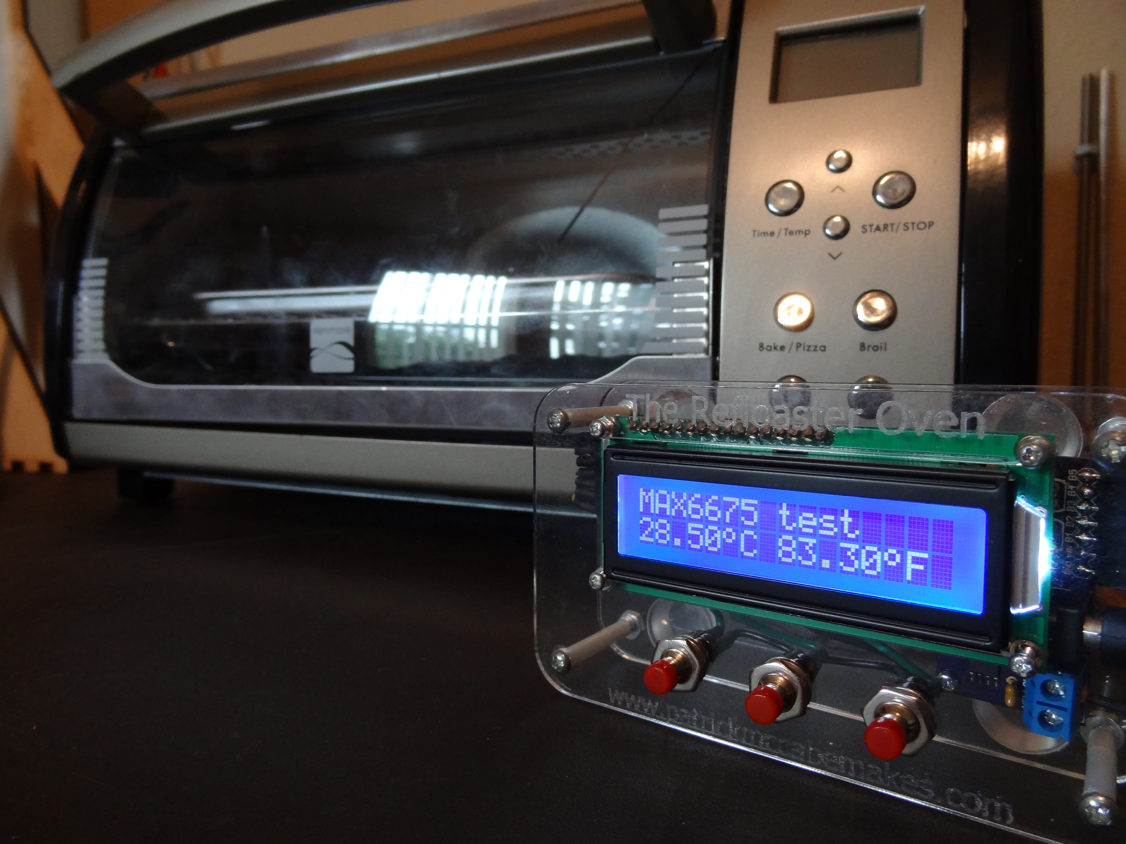
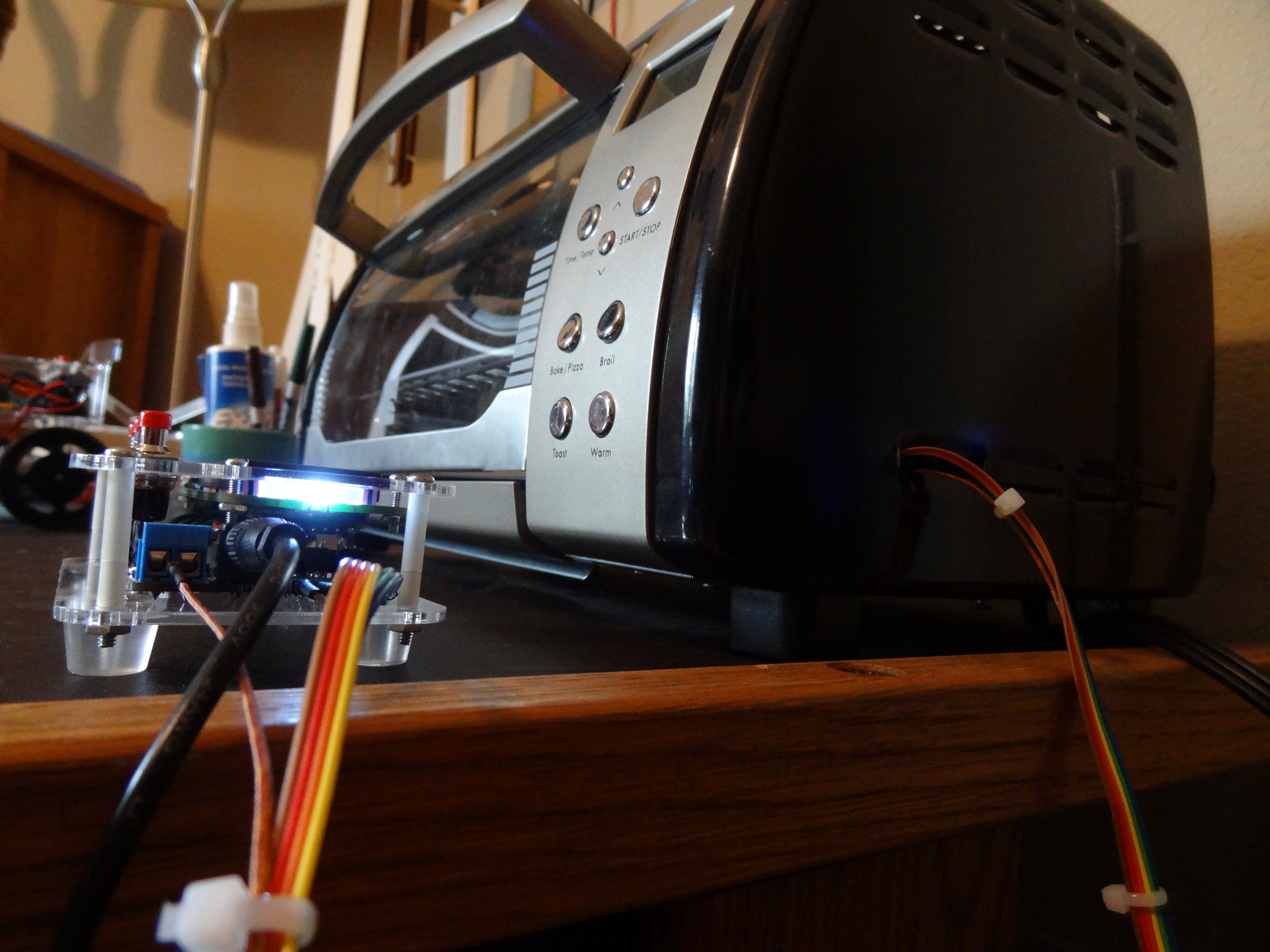
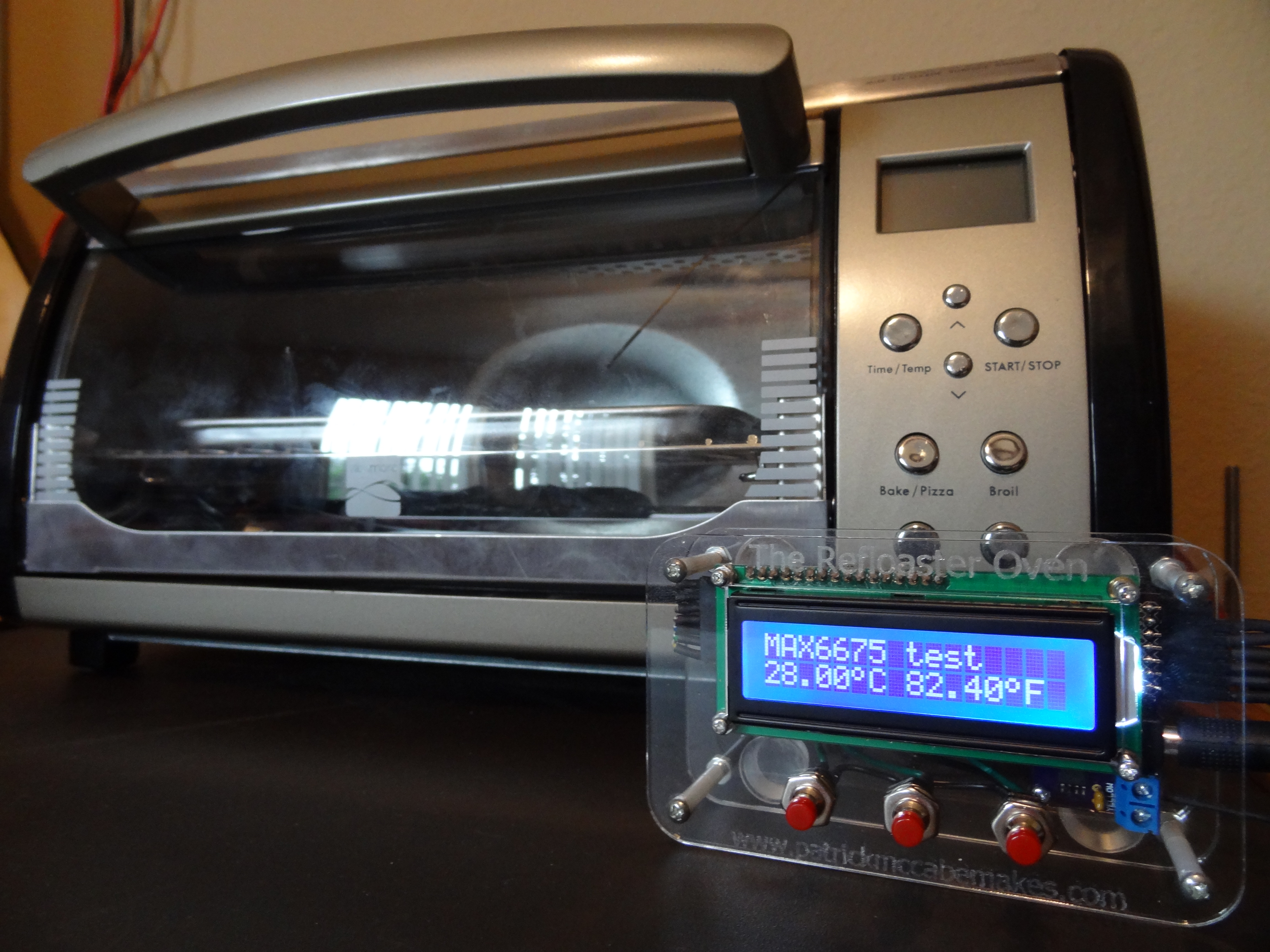
Testing
Images from a simple thermocouple test program:
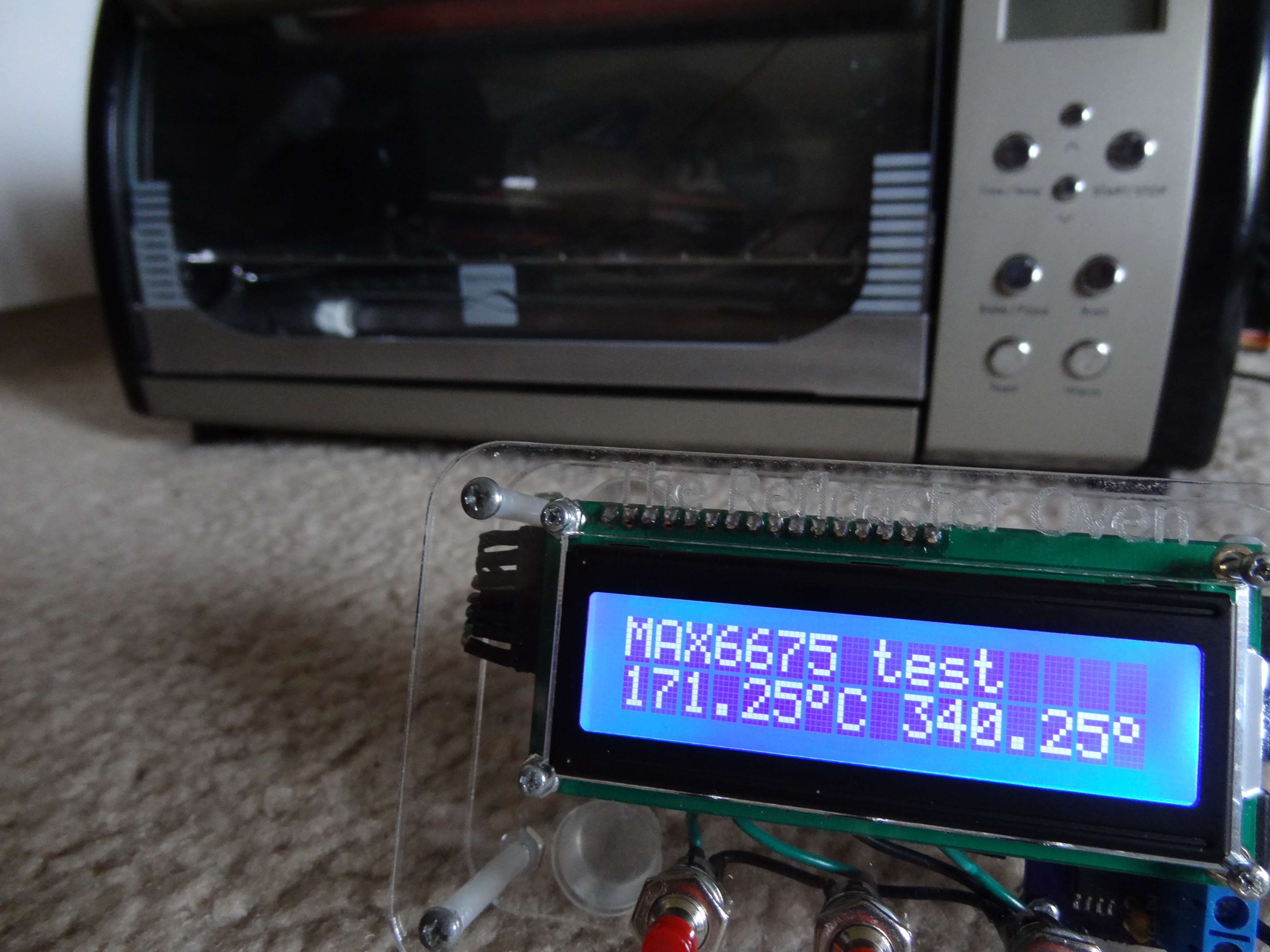
The "Final Product"